Creation of Multiple viewports, Scaling the drawing and setting in Template in AutoCad
Aim:
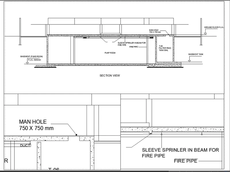
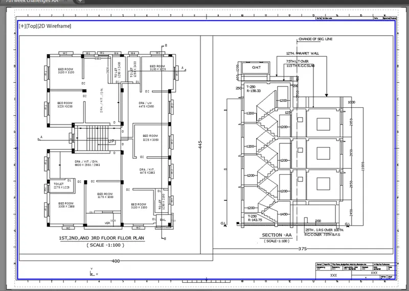
To Create the Create a layout of the Plan and Section A of the project in Challenges 7.
Introduction :
Various command used while Sketching :
- Line command
- Units command
- Lim max command
- XL command
- Zoom command
- Text command
- Rectangle command
- Copy command
- Dimension command
- Layout command
- Limits command
- Rename command
- View command
- MS spaces command
- PS Space command
- UCSICON command
- PROPERTIES command
- MVIEW command
- PAN command
PRODUCTRE :
STEP 1 :
- GO to START MENU ,select AutoCAD 2018.
- Enter “UNITS” command in the command tab.
- Open “ Drawing units “ dialogue box , Type as “Decimal ” and precision as 00
- Then click units scale to “ millimetres ”
- Click “OK”.
- Enter “ LIM MAX” command in the command tab.
- Enter new value for Lim max as 30000’.
- Enter “zoom” command in the command box.
- Enter “All” command in the command box.
- Enter “LIMITS” command in the command box.
- Specify lower left corner as “0,0”
- Specify right corner as “28000,28000”
- Enter “zoom “ command in the command box.
- Enter “ALL” command in the command box.
Step 2:
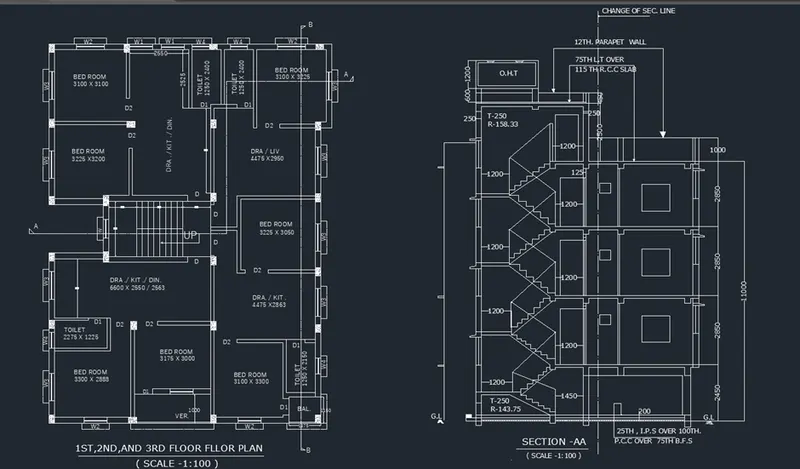
- We are already created the drawing in 7th week challenges using various command .
- Enter “LAYOUT” command in the command box.
- Select “TEMPLET” command in the command box.
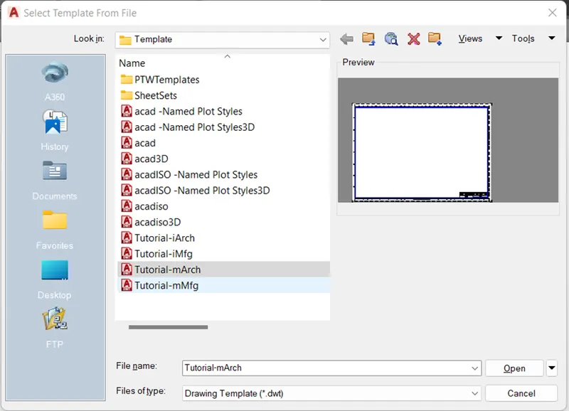
- U will get dialoge box called “Select Templet from file”
- Select “Tutorial-mArch” and
- Click “OPEN”
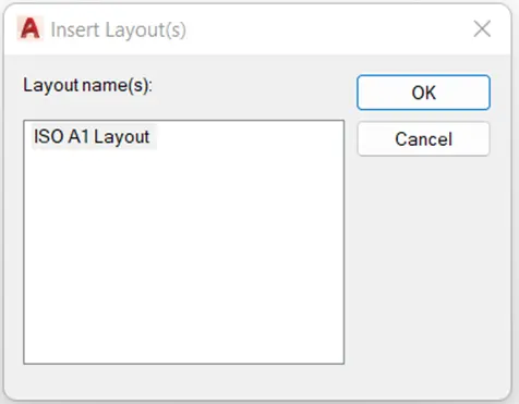
- And u will get another dialoge box “INSERT LAYOUT (S)”
- Click “OK”
- U will get layout sheet called “ISO A1 LAYOUT”
- Enter “View” command in the command box
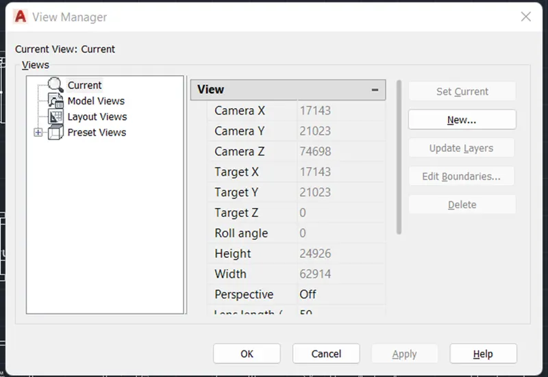
- U will get dialoge box called “VIEW MANAGER “
- Select “NEW” in the dialoge box.
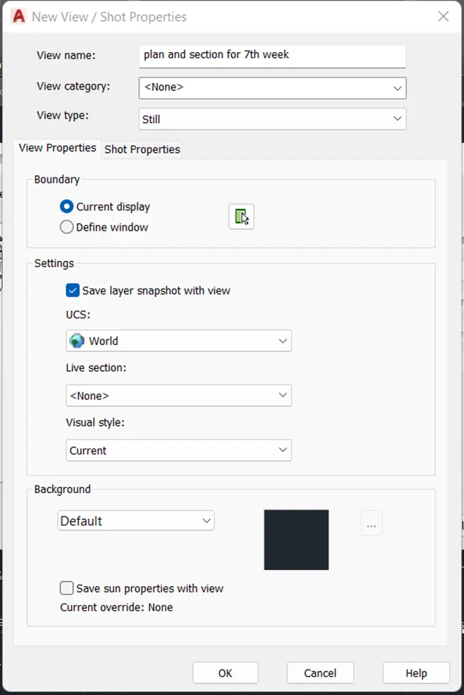
- U will get dialoge box called “NEW VIEW / SHOT PROPERTIES”
- I Given view name as “PLAN AND SECTION FOR 7TH WEEK”
- Click “SELECT” option in the dialoge box.
- Select the ““PLAN AND SECTION”
- Click “ENTER” then again u will get a dialoge box .
- Click “OK “ in the dialoge box.
- Go to the ““ISO A1 LAYOUT”
- Enter “MV” command in the command box.
- Click “FIT “in the command box
- Enter “MS” command in the command box .
- Unlock the lock icon
- Adjust the drawing as per the question
- Enter “CTRL+P” command
- Take a print out as printout as the question
- The finally show the result
RESULT:
AIM:
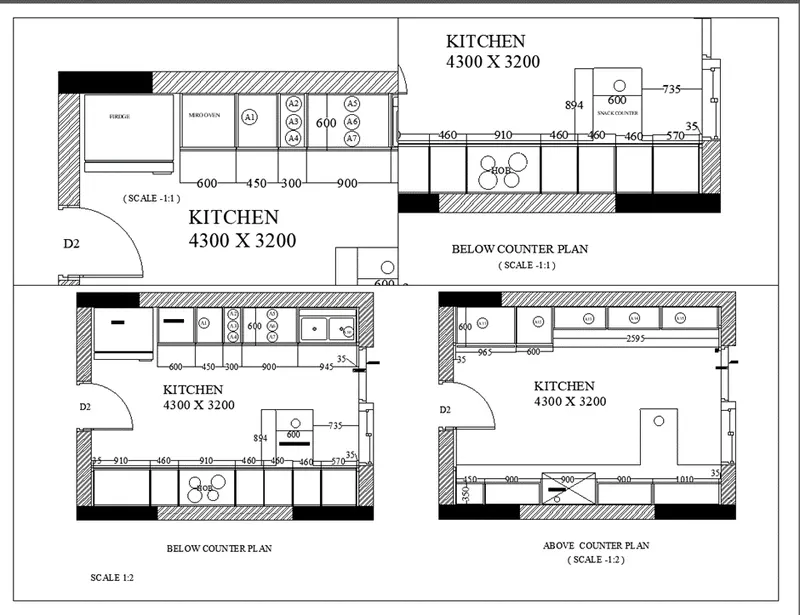
To Create a layout of the Kitchen drawn in Challenge 9 as shown in Figure
Introduction :
Various command used while Sketching :
- Line command
- Units command
- Lim max command
- XL command
- Zoom command
- Text command
- Rectangle command
- Copy command
- Dimension command
- Layout command
- Limits command
- Rename command
- View command
- MS spaces command
- PS Space command
- UCSICON command
- PROPERTIES command
- MVIEW command
- PAN command
PRODUCTRE :
STEP 1 :
- GO to START MENU ,select AutoCAD 2018.
- Enter “UNITS” command in the command tab.
- Open “ Drawing units “ dialogue box , Type as “Decimal ” and precision as 00
- Then click units scale to “ millimetres ”
- Click “OK”.
- Enter “ LIM MAX” command in the command tab.
- Enter new value for Lim max as 30000’.
- Enter “zoom” command in the command box.
- Enter “All” command in the command box.
- Enter “LIMITS” command in the command box.
- Specify lower left corner as “0,0”
- Specify right corner as “28000,28000”
- Enter “zoom “ command in the command box.
- Enter “ALL” command in the command box.
Step 2:
- We are already created the drawing in 9th week challenges using various command .
- Enter “View” command in the command box
- U will get dialoge box called “VIEW MANAGER “
- Select “NEW” in the dialoge box.
- U will get dialoge box called “NEW VIEW / SHOT PROPERTIES”
- I Given view name as “KITECHEN”
- Click “SELECT” option in the dialoge box.
- Select the ““KITECHEN LAYOUT”
- Click “ENTER” then again u will get a dialoge box .
- Click “OK “ in the dialoge box.
- Go to the “LAYOUT 1”
- Enter “MV” command in the command box.
- Select “3” in the command box
- Click “ENTER” and select “HORIZONTAL, VERTICAL, ABOVE , BELOW, LEFT, RTIGHT” which you want as per the drawing
- Click “FIT “in the command box
- Enter “MS” command in the command box .
- Unlock the lock icon
- Adjust the drawing as per the question
- Enter “CTRL+P” command
- Take a print out as printout as the question
- The finally show the result
RESULT:
AIM:
To Create a layout of the section created in Challenges 9
Introduction :
Various command used while Sketching :
- Line command
- Units command
- Lim max command
- XL command
- Zoom command
- Text command
- Rectangle command
- Copy command
- Dimension command
- Layout command
- Limits command
- Rename command
- View command
- MS spaces command
- PS Space command
- UCSICON command
- PROPERTIES command
- MVIEW command
- PAN command
PRODUCTRE :
STEP 1 :
- GO to START MENU ,select AutoCAD 2018.
- Enter “UNITS” command in the command tab.
- Open “ Drawing units “ dialogue box , Type as “Decimal ” and precision as 00
- Then click units scale to “ millimetres ”
- Click “OK”.
- Enter “ LIM MAX” command in the command tab.
- Enter new value for Lim max as 30000’.
- Enter “zoom” command in the command box.
- Enter “All” command in the command box.
- Enter “LIMITS” command in the command box.
- Specify lower left corner as “0,0”
- Specify right corner as “28000,28000”
- Enter “zoom “ command in the command box.
- Enter “ALL” command in the command box.
Step 2:
- We are already created the drawing in 9th week challenges using various command .
- Enter “View” command in the command box
- U will get dialoge box called “VIEW MANAGER “
- Select “NEW” in the dialoge box.
- U will get dialoge box called “NEW VIEW / SHOT PROPERTIES”
- I Given view name as “LAYOUT OF SECTION IN CHALLENGE 9
- Click “SELECT” option in the dialoge box.
- Select the “LAYOUT OF SECTION IN CHALLENGE 9”
- Click “ENTER” then again u will get a dialoge box .
- Click “OK “ in the dialoge box.
- Go to the “LAYOUT 1”
- Enter “MV” command in the command box.
- Select “3” in the command box
- Click “ENTER” and select “HORIZONTAL, VERTICAL, ABOVE , BELOW, LEFT, RTIGHT” which you want as per the drawing
- Click “FIT “in the command box
- Enter “MS” command in the command box .
- Unlock the lock icon
- Adjust the drawing as per the question
- Enter “CTRL+P” command
- Take a print out as printout as the question
- The finally show the result
RESULT: