Creation of Multiple viewports, Scaling the drawing and setting in Template in AutoCad
QUESTION-1:
Create a layout of the Plan and section A of the project in challneges7 using the template Tutorial-march.dwt in a scale as given in the Viewport of the size as shown in fig .Also use attedit command to edit the information in the title block Use A1 size for the layout. Take a polt.
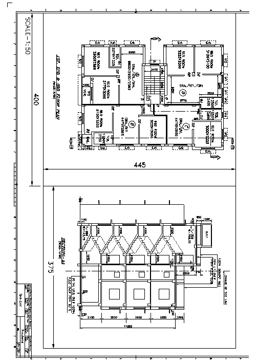
ANSWER:
AIM: To create the layout of the plan and section A of the project in challnge 7 using the template Tutorial- mArch .dwt.
INTRODUCTION:
- A layout templte is a layout imported from a DWG or DWT file.the program has sample layout templates to use whwn we designe a new layout environment.
- When you create a layout based on a template the page setup and paper space objects insluding any viewport objectsare used in the new layout.No model space objects are imported.
- The layout templates are identified with a dwt file extension.Howeever a layout template or layout from any drawing or drawing template can be imported into the current drawing.
COMMANDS USED:
- Units.
- Limits.
- Xref.
- Layout.
- Attedit
- Multiple viewports.
- Model space
- Paper space.
- Print.
PROCEDURE:
STEP-1:
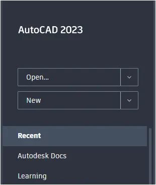
- Open the AUTOCAD SOFTWARE from the desktop.
- On the home page of the AUTOCAD ,click on New drawing.
STEP-2:
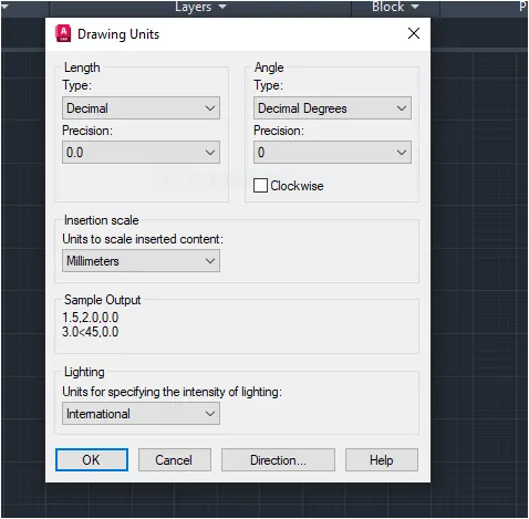
- Type UN and set the units as Decimal and precision as 0.0
- Set the units as milimeters in the insertion scale.
- Type Limits in the command box and set the Lower limit as 0,0 and upper limit as 10000,10000
- Type Z enter for zoom Enter and A enter for Zoom all.
STEP-3:
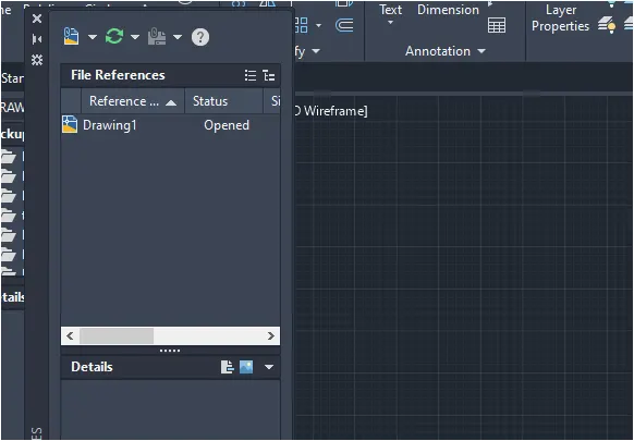
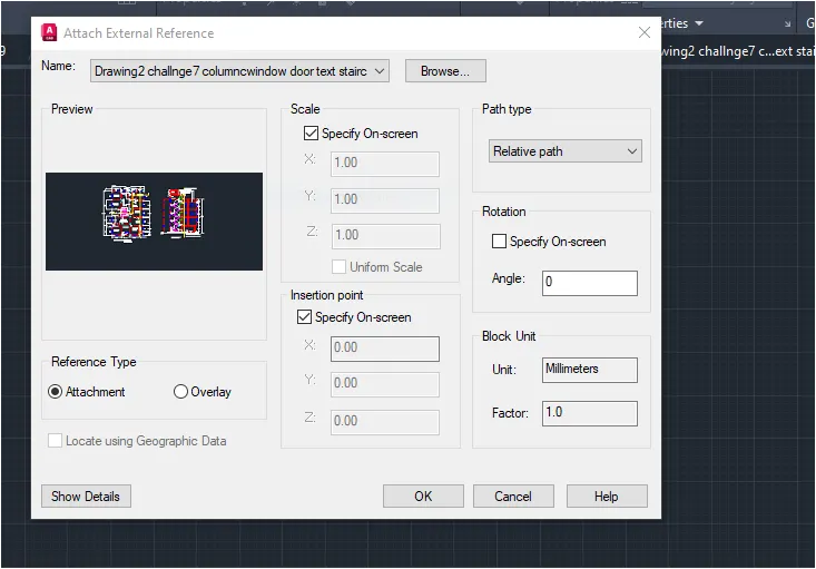
- Go to extranal referance by typing Xref in the command box.
- Then attach the DWG file of the challnge 7 that we created earlier.
STEP-4:
- Select the DWG file and set the Reference type as an Attachment.
- Specify the scale as on the screen and insertion points as on the screen.
- Then click ok to the load the challenge 7 drawing into the screen.
STEP-5:
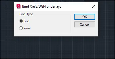
- After attaching the drawing,select the drawing and left-click attached drawing.
- Then Select bind typa as Bind and press ok.
STEP-6:
- Type Layout in the command box to open the new layout.
- Type New in the command box and rename it as plan section.

STEP-7:
- From the floor pla drawing Click left click of layout tab.
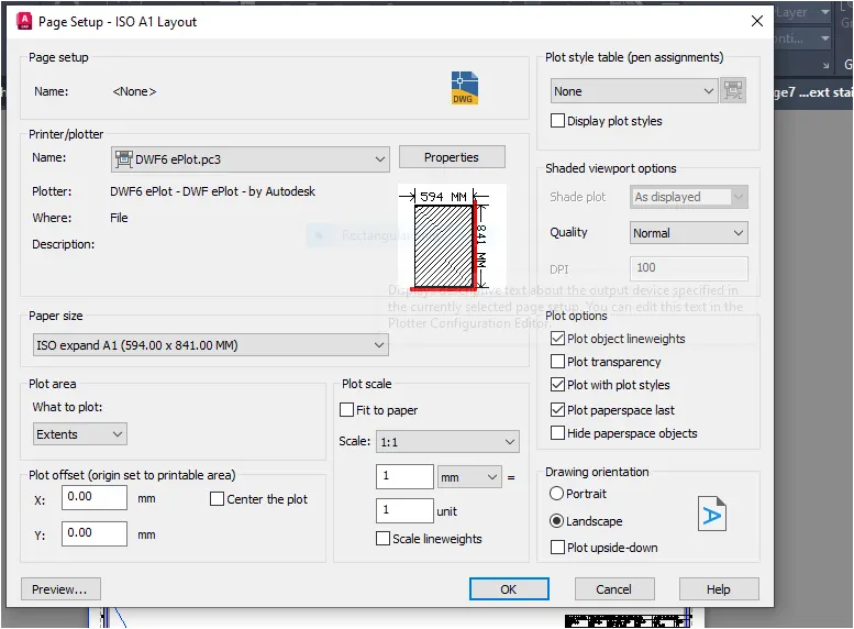
- Setup Page setup manager.
- Choose paper size as A1.
- Then click on ok.
Step-8:
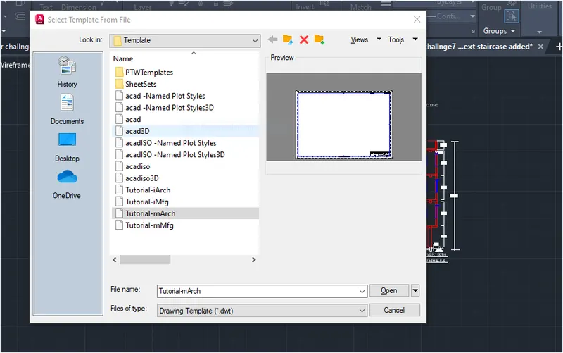
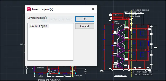
- Right click on the plan and section Layout from the layout tab.
- Select the option called from the template option.
- Select the Template file to load into the drawing.
- Select the template file as Tutorial-mArch.dwt
- Then click open to load the template into the layout.
Step-9:
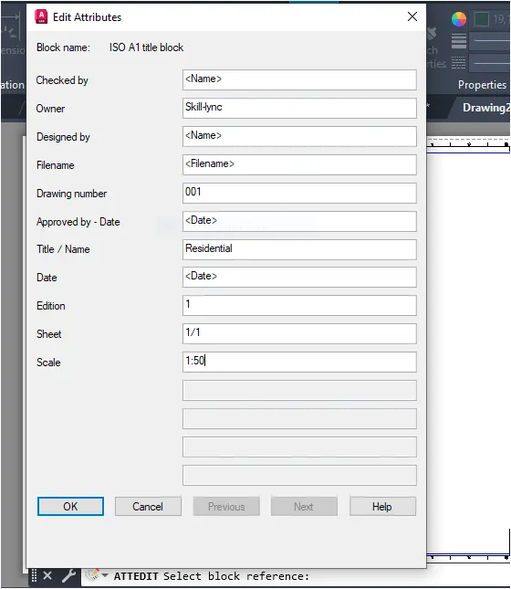
- After Loading the Layout template into the drawing now we have to change the attributes.
- Type ATTEDIT in the command box to open the edit Attributes dialog box.
- Rename the title blocks as shown in the figure below.
- After completing changes in the edit Attributes ,Click on ok to make changes.
STEP-10:
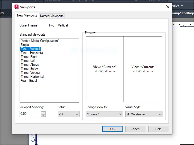
- Open the viewports dialog box by typing MV in the command box.
- Select the viewports type as Two: vertical as shown in the fig below.
- Adjust the viewports spacing according to the requirement.
STEP-11:
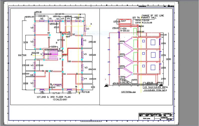
- After Creating the multiple viewports ,now we have to adjust the xooming and scalling.
- Type MS in the command box to switch the mode into model space.
- Adjust the visibility of the plan and section using the pan tool.
- Adjust the scaling as per the given requirement.
STEP-12:
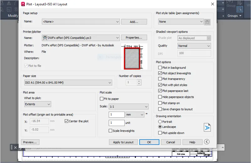
- Now type polt in the command box to open the olit and a print dialog box.
- Select the polt type as DWFx poly.pc3 and paper size as ISO A1
- Select the Plot area as Extents and scale as 1:1 as per the given requirement.
STEP-13:
- Then click on preview to see the preview of the Layout.
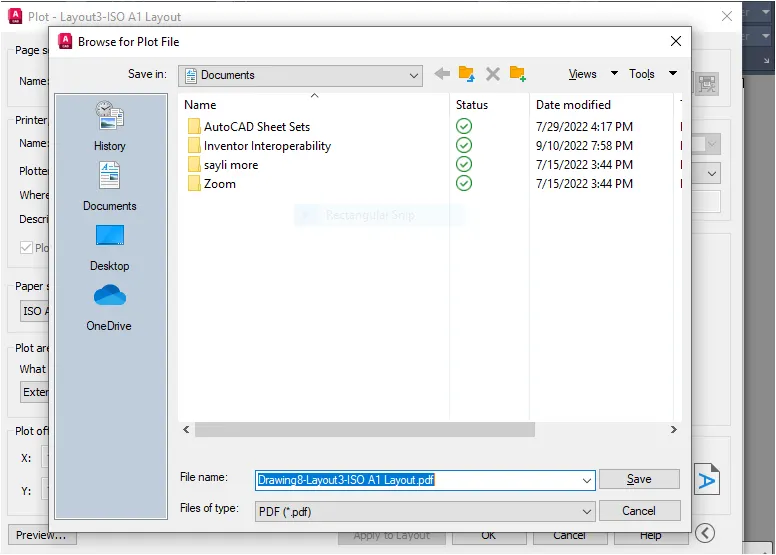
- After Settling hace been made,click on ok to print or save it to the local folder.
RESULT:
- The Layout of the plan and Section-a has been Printed or plotted Successfully using the Viewports and Tutorial-mArch .dwt template.
QUESTION-2:
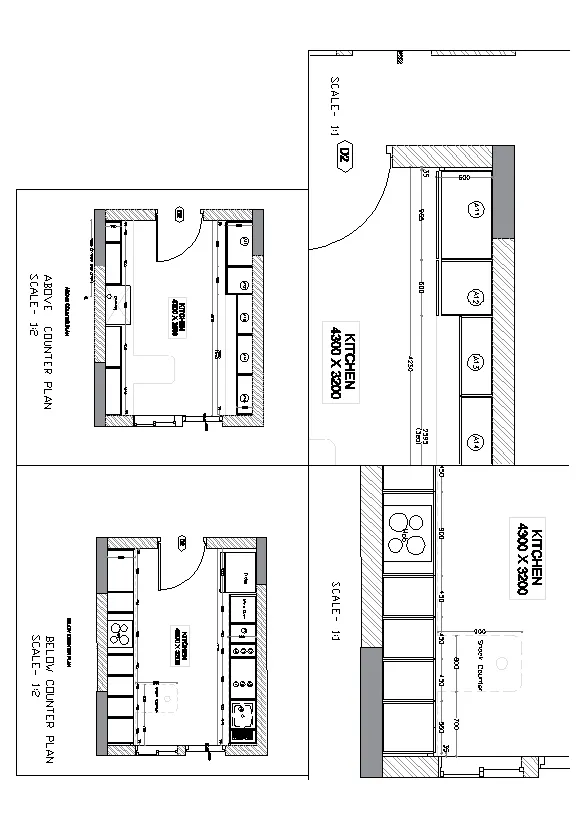
Create a alyout of the kitchen drawn in challnge 9 as shown in fig use the scale as shown in the figure .use an A4 size page for the Layout.take a polt.
ANSWER:
AIM: To create the Layout of the kitchen drawn in challnge 9 using the appropriate scale and A4 size page.
INTRODUCTION:
- A layout template is a layout imported from a DWG or DWT file.The porgam has sample layout templates to use when we design a new layout environment.
- The kitchen layout is the shape that is made by the arrangement of the counter top major appliances and storage areas. the layout and floor plsn create the kitchen primary work triangle which is the path that you make when moving from the refrigerator to the sink to the range when preparing a meal.
Commands used:
- Viewports
- Multiple views.
- Model space.
- Paper space.
- Pan.
PROCEDURE:
STEP-1
- Open the AUTOCAD application from the desktop.
- On the AUTOCAD homepage,click on open drawing.
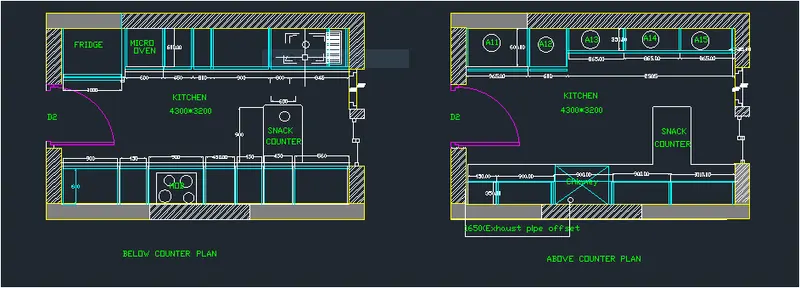
- Open the kitchen layout drawing that we created in the challnge9.
STEP-2:
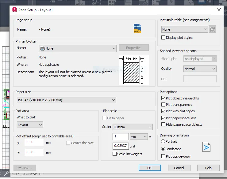
- From the floor plan drawing click left click of Layout tab.
- Select Page setup Manager.
- Choose paper size as A4.
- Then click ok.
SETP-3:
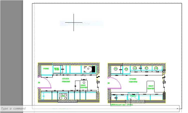
- In the command prompt write layout.
- Select New and choose suitable name.
- From the layout area command MVIEW.
- Select the polt area and paste the object.
STEP-4:
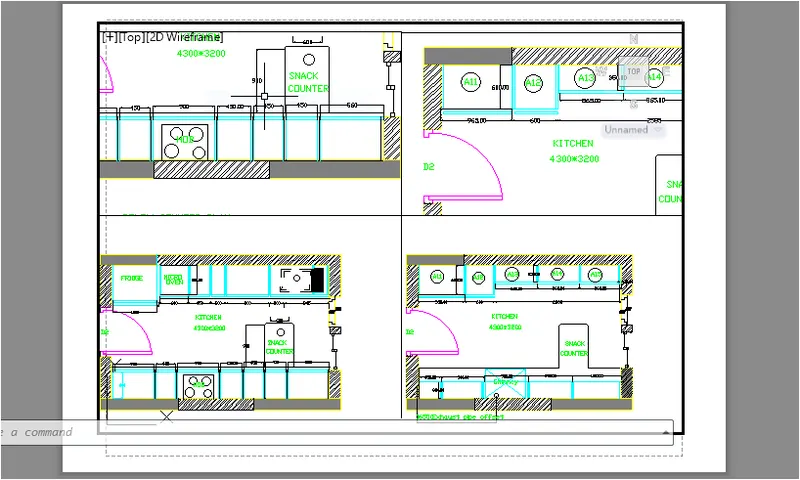
- In the polt area type MSVIEW.
- Select the area and paste another object to show.
- Use MS and PS commands for edititing and zooming the object inside plot area.
STEP-5:
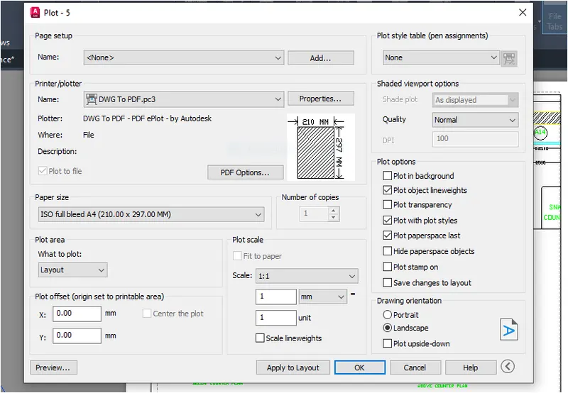
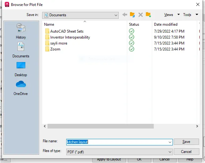
- Now type polt in the command box to open the polt and a print dialog box.
- Select the polt type as DWG to PDF pc3 and paper size as ISO A1.
- Select the polt area as exteents and scale as 1:1 and 1:2 as per the given requirement.
STEP-6:
- Then click on preview to see the preview of the layout.
- After setting have been made ,click on ok to print or save it to the local folder.
RESULT:
- The different views of the kitchen layout have been plotted and printed successfully with four equal viewports using appropriate scaling and an A4 sheet.
QUESTION-3:
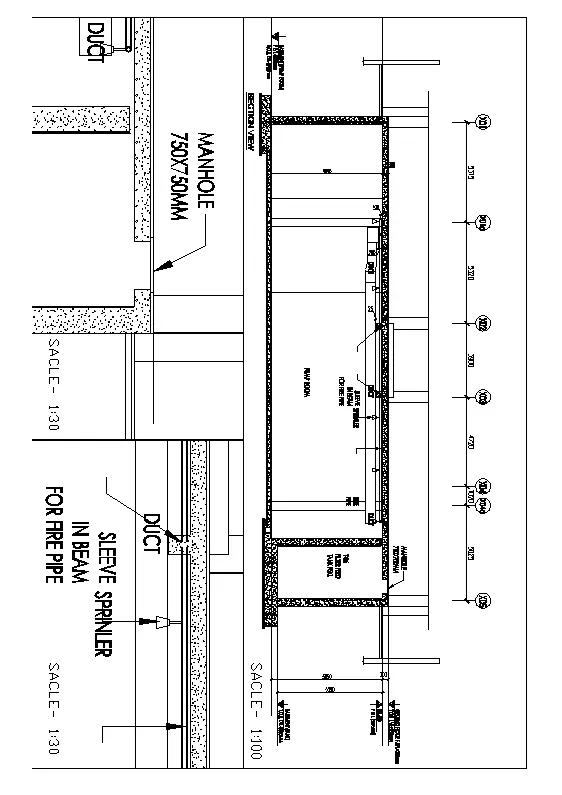
Create a layout of the section created in challnges 9. Use the scale as mentioned in the figure.use the MV command to create multiple viewports.Take a plot.
ANSWER:
AIM : To create the layout of the section created in challnge 9 using appropriate scalling and multiple viewports.
INTRODUCTION:
- A section view provides architects and contractors another way of understanding how construction will stand up as it reveals details of the construction of walls and the thickness and height of beams and other supports. While a floor plan allows for a view of how the walls stand about each other a section shows where the wall meets the floor and te distnce that separates one floor from another.
- Finally sections provide a better understanding of how a building spaces will accommodate its future occupants and whether for example the ceiling will feel like it looms or soars overhead.
COMMANDS USED:
- Viewports.
- Multiple views.
- Model space.
- Paper space.
- Pan.
- Print.
PROCEDURE:
STEP-1:
- Open the AUTOCAD Application from the desktop.
- On the AUTOCAD homepage ,click on open drawing.
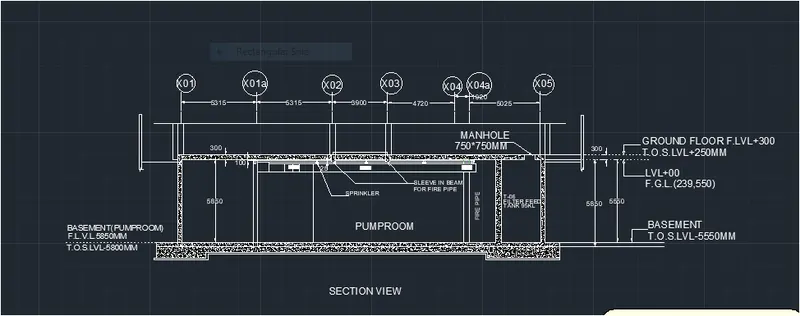
- Open the section drawing of the industrial plan that we created in the challenge 9.
STEP-2:
- Now we have to create the various views of the kitchen layout from the view tab.
- Go to the View tab and select the option called New view.

STEP-3:
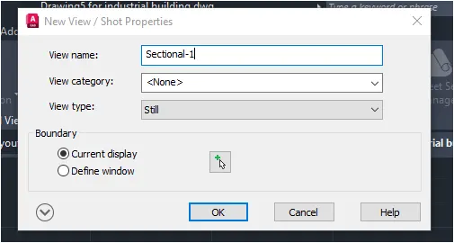
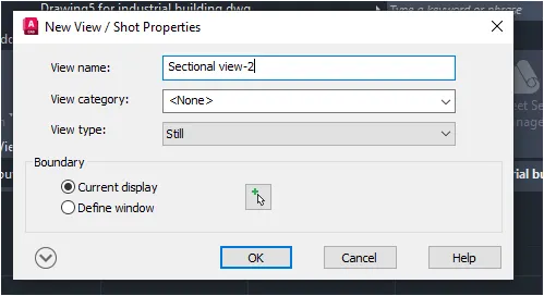
- After clicking on the New View option a New view dialog box will appear.
- Create the view name as Sectional view-1 and Boundary as Current display.
- After making change s,click on ok and then close the dialog box.
- Similarly create another view as sectional view-2 using the view tab.
STEP-4:
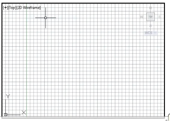
- Type Layout in the command box to open the new layout.
- Type New in the command box and rename it as section view of industrial layout.

- After making changes a new layout will appear on the screen.
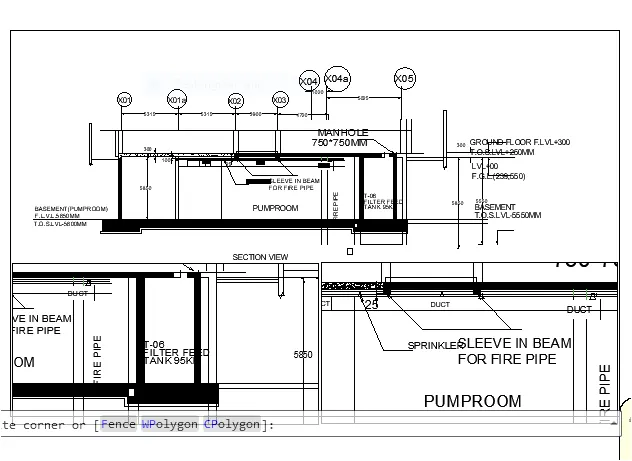
STEP-5:
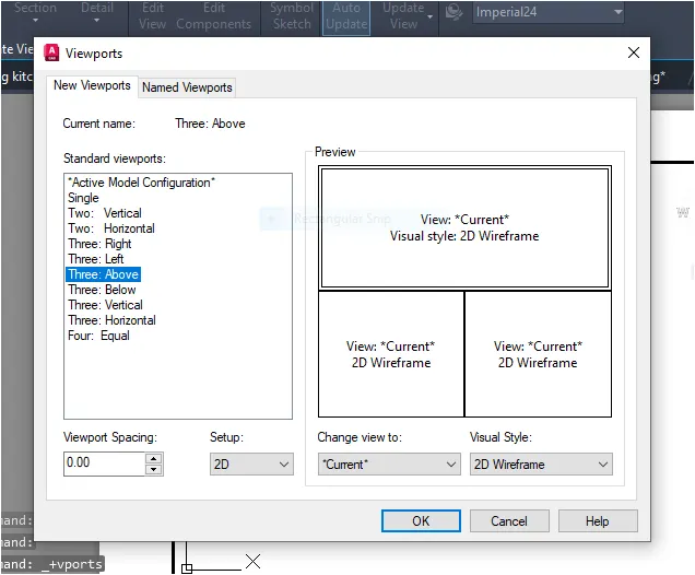
- Open the viewports dialog box by typing MV in the command box.
- Select the viewports type as FOUR: Equal as shown in the figure below.
- Adjust the viewports spacing according to the requirement.
STEP-6:
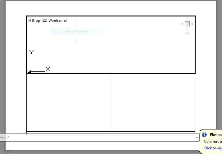
- After Creating the multiple viewports ,now we have to adjust the zooming and scaling.
- Type MS in the command box to switch the mode into Model space.
- Adjust the visibility of the plan and section using the pan tool.
- Adjust the scaling to 1:30 as per the given requirements.
STEP-7:
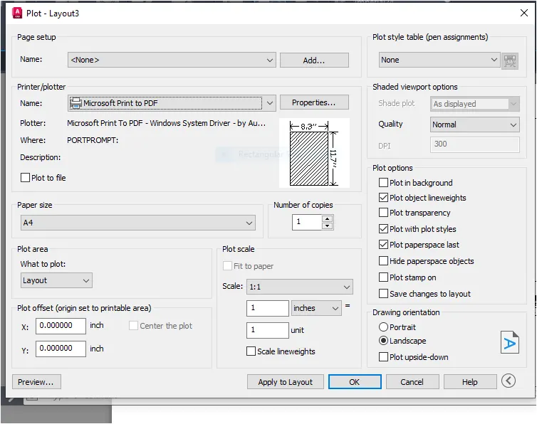
- Now Type Plot in the command box to open the Plot and a print dialog box.
- Select the Plot type as Microsoft Print to PDF and paper size like A4.
- Select the plot area as extents and scale as 1: 30 as per the given requirement.
STEP-8:
- Then Click on Preview to see the preview of the layout.
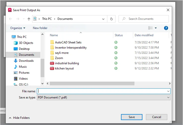
- After Settings have been made,click on ok to print or save it to the local foder.
RESULT:
- The Different views of the Sectional industrial building have been pooted successfully using multiple viewports and appropriate scale.