Creation of Multiple viewports, Scaling the drawing and setting in Template in AutoCad
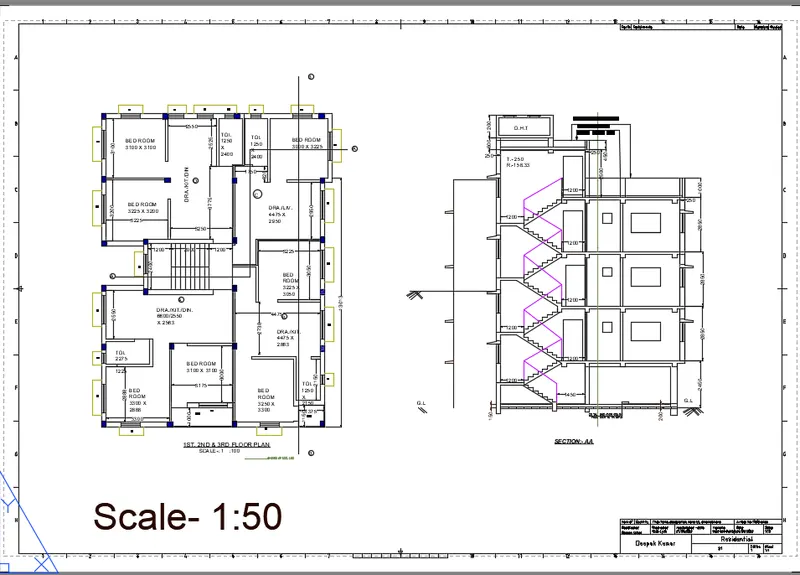
1. . Creating a layout of the Plan and Section A of the project in Challenges 7, using the template Tutorial-mArch.dwt in a scale as given in the Figure in A1 size papaer and using MV command to create the viewport of the size as shown in Figure. Also, Editing the Title Block using ATTEDIT command. finally plotting the Layout.
:- First of all open the Floor plan and Elevation section drawing created in the challange-7 in CAD file.
:- Now take new layout and Name it as Floorand Elevation Section and Go to page setup manager.
:- In page set-up manager name the file as DWG to PDF and Set the size of the page as ISO A1.
:- Now With MV command Create a View port for Floor Plan and Elevation section and with "MS" command zoom the section.
:- Now with PS command Come to paper space and set the scale of 1:50.
:- Now create a new layout and open template and set tempalte mArc.dwt.
:- take PS Command and come to paper space and take the drawing at center and check the scale of 1:50.
:- Using Attedit command edit the Title Block attributes like Owner name, etc.
:-Now with plot command plot the Vport in PDf, Save it and take screen shot of it.
:- Take the text command and write the text " Scale-1":50".
:- Thus we have created the View port in The Template mArc.dwt inscale of 1:50.
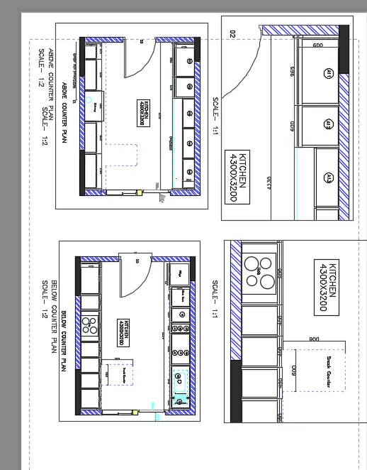
2.0 Creatin a layout of the Kitchen drawn in Challenge 9 as shown in Figure using the scale as shown in the Figure in A4 Size page for the layoutand ploting it.
:- First of all open the Kitchen section drawing created in the challange-9 in CAD file.
:- Now take new layout and Name it as Kitchen section Section and Go to page setup manager.
:- In page set-up manager name the file as DWG to PDF and Set the size of the page as ISoA4 ( 210 X 297 mm).
:- Now With MV command Create a View port for Above counter Plan and with "MS" command zoom the section.
:- Now with PS command Come to paper space and set the scale of 1: 2.
:- Again with MV command create a vport for above counter plan counter section and zoom with MS command.
:- With PS command go to papaer space and set the scale of 1:1.
:- Again with MV command create a Vport for below counter plan.
:- Now take MS command and Go inside the model and zoom it.
:- Now take PS command and Go to paper space and set the scale of 1:2.
:- Now again with MV command create a Vport for abiove counter HOB Section and with MS command Zoom it.
:- take PS command and Set the scale as 1:1.
:- take the Text command and write the SCALE for all.
:- Finally Plot the Vport in PDF and save it and take screen shot to insert here.
:- Hence the View port of the Layout of Kitchen above and Below counter plan have been Created as shown below.
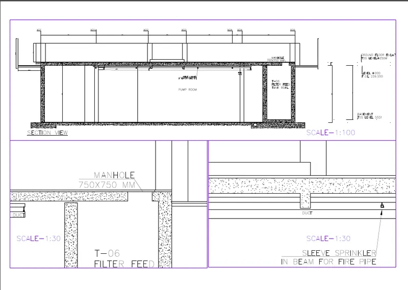
3.0 To create the layout of the section-created in the challange-9 and also creat View ports using MV command and Plot it.
:- First of all open the Portal section drawing created in the challange-9 in CAD file.
:- Now take new layout and Name it as Portal Section and Go to page setup manager.
:- In page set-up manager name the file as WG to PDF and Set the size of the page as A3 ( 420X 297 mm).
:- Now With MV command Create a View port for Portal full section and with "MS" command zoom the section.
:- Now with PS command Come to paper space and set the scale of 1: 100.
:- Again with MV command create a vport for MANHOLE and zoom with MS command.
:- With PS command go to papaer space and set the scale of 1:30.
:- Again with MV command create a V=port for DUCT and Sleeve sprinkler.
:- Now take MS command and Go inside the model and zoom it.
:- Now take PS command and Go to paper space and set the scale of 1:30.
:- Now Take TEXT command and write the text for SCALE. and Plot in PDF and Save it.
Hence the Layout of the Section and View Ports have been Created as shown in the drawing below and Ploted here.