Creation of Multiple viewports, Scaling the drawing and setting in Template in AutoCad
AIM: To Creat the Multiple viewports, scaling the drawing and setting in Template in AutoCAD.
INTRODUCTION:
There are two types of viewports in AutoCAD: Model space viewport and layout space viewport
Viewports are areas that display different views of your drawing or model
- Layout vewport are object it you can scale to display the vide of your drawing on a layout tab for publising and production.
- Model viewports split the drawing space into one or more rectangular areas called model space viewports
In large or complex drawing, displaying different views reduces the time needed to zoom or pan in a single view. This viewport can be comfigured from the view tab on the ribbon.
There are different model spave viewports cofigurations like single, two, vertical , horizontal etc., These configurations can be saved and restored by name with the VPORTS command or pulling down the viewport cofiguration form the ribbon.
When using multiple vieports, the one that is highlighted with a blue rectangle is called the current viewport, the remaining viewports will be displayed grey as for not used.
General Commands are used for Diagram:
- Line: Used to draw different entities like walls windows etc.
- Xline or Construction line: This is used to draw infinite lines which are very much essential in developing sections and elevation.
- Offset: This command also used ectensively to develop the same properties' to the copy of another one
- Trim: This tools is used to remove or erase the unwanted line.
- Extend: It is used to extend a line to joint the edge of another line or opposite line.
- Mirror: This tool is used to mirror/flip an object.
- Hatch: This tool is used to provide the approriate hatching to defferent portions.
- Fillet: This tool is very much essential in developing corners wherer the radius can be provided as whatever need.
- Layer: This enable such to assign different properties to different entities in a very easy way.
- Block: This feature is useing for any kind of material like furnitures, door, window etc., are creat with differend size and to insert the wherever its need in the plan form directly taken in the Blocks.
- Annotation: In this command are used for mention the Text and Dimension of the plan.
DEFAULT PROCEDURES:
- Open the AutoCAD application from my desktop
- Click file menu select New to creat a New Diagram
- Select Default setting for Metric (Milli Meter) or Imperial (feet and inches) setting for whatever need for Given diagram
- In default setting click is use a wizard and in that advance setting and set unit as Decimal, Engineering,or Architectural Etc. precission as 0 Press Enter.
- Set Angle Measurement as EAST
- Set Angle Direction as Counter-Clockwise direction
- Set Area of drawing provides for as per given diagram size, Because of will Draw the whole drawing for in single page or separate New sheet.
- Finish
- And Keep Ortho ON And where its neccesary to off the ortho can off
- Object snap ON
- Enter.
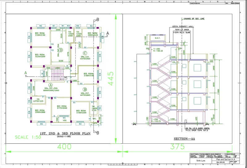
1. Create a layout of the Plan and Section A of the project in Challenges 7, using the template Tutorial-mArch.dwt in a scale as given in the Figure. Use the MV command to create the viewport of the size as shown in Figure. Also, use ATTEDIT command to edit the information in the title block. Use A1 size for the layout. Take a plot.
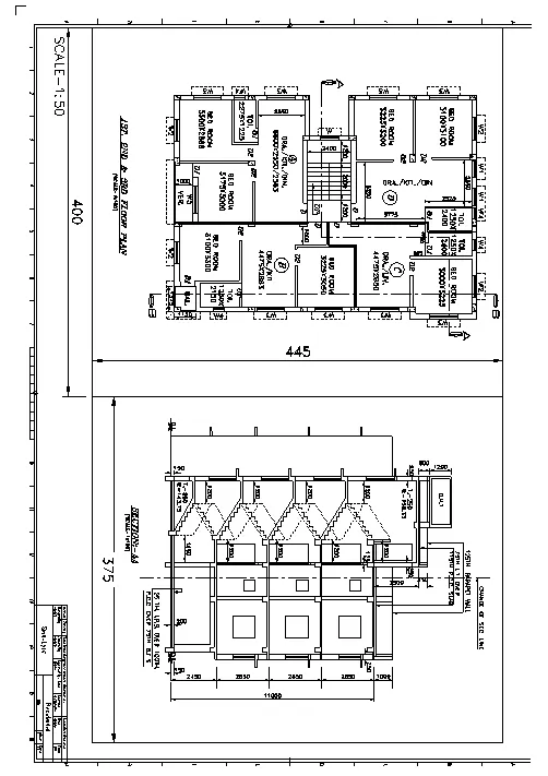
AIM: To create layout of the plan and section A of the project in challenge7 as shown in the figure
INTRODUCTION: The layout is created in AutoCAD by using the template Tutorial-mArch.dwt in a given scale
PROCEDURE:
STEP 1) MODEL FOR DRAWING
- Open week 7 challenge in AutoCAD
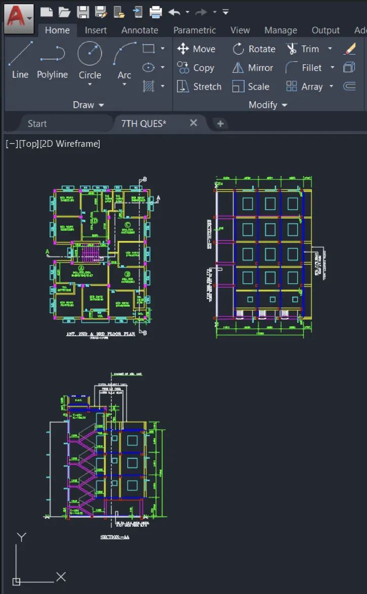
STEP 2) CREATE NEW VIEW
- Zoom the Plan which is cover entire screen
- Click on the VIEW ribbon
- In the NAMED VIEWS tool click on NEW VIEW
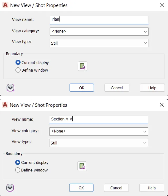
- A dialog box is opened
- Specify View Name as Plan
- Repeat for section A
STEP 3) CREATE VIEW PORT
- In the Model Viewports Tool
- Click to drop down Viewport Configuration and select TWO: VERTICAL
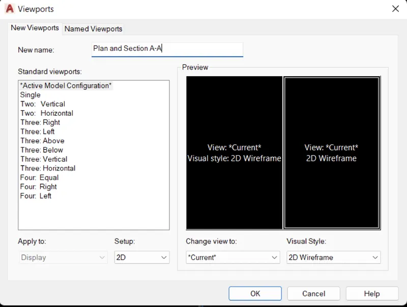
- Click on the NAMED, a dialog box open as viewports
- Go to new viewports tab and type new name as Plan and Section A-A
STEP 4) CREATE LAYOUT
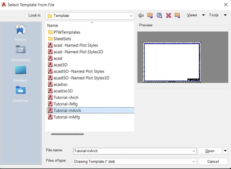
- Enter Layout command
- Click on Template option
- Select Tutorial mArch and open
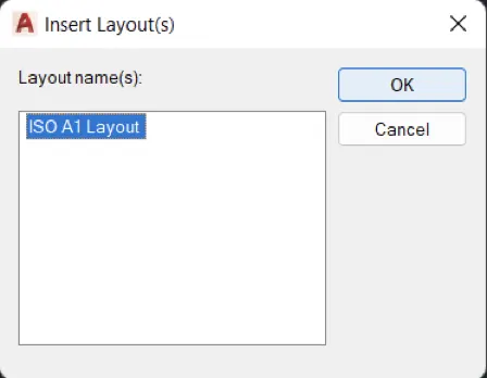
- Click OK in Insert Layout dialog box
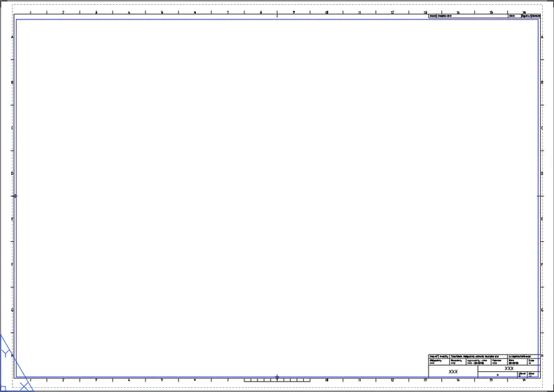
- A model tab is added as ISO A1 Layout
- Right click on the ISO A1 tab to rename as Plan and Section A-A
STEP 5) PAGE SETTING
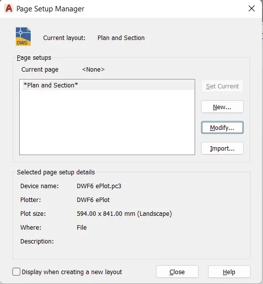
- Enter PAGESETUP command
- A dialog box shows of Page Setup Manager
- Click on Modify
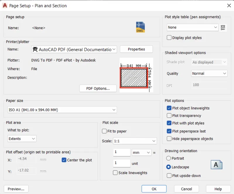
- New dialog box shows of Page Setup
- Change Printer/Plotter name as AUTOCAD PDF (General Documentation).pc3
- Change page size as ISO A1 (841.00 X 594.00 MM)
STEP 6) INSERT DRAWING
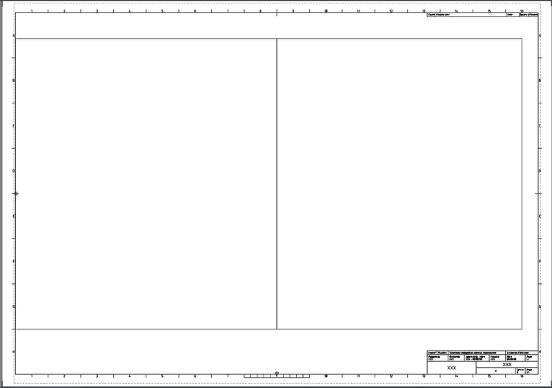
- Select to delete existing drawing in current page
- Set current layer as Title Block from layer property
- Enter REC command for rectangle
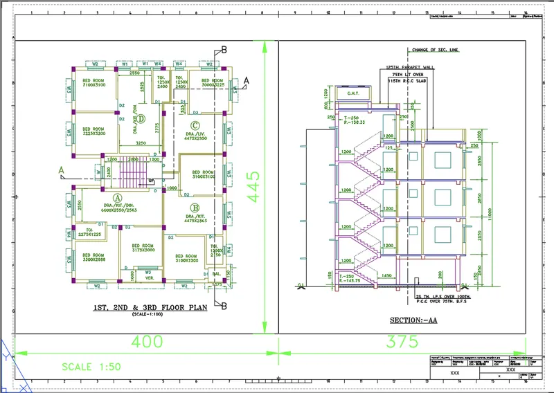
- Create two rectangles of size 400x445 and 375x445
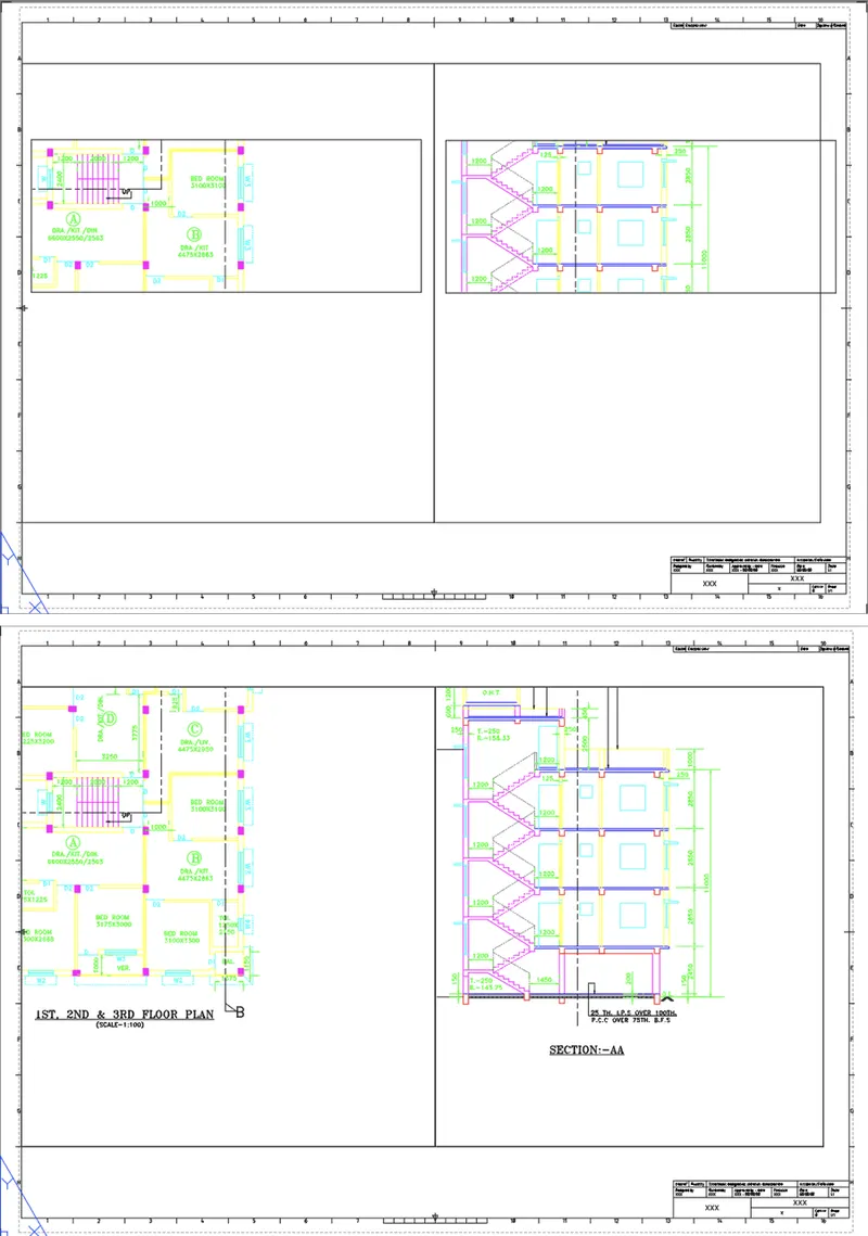
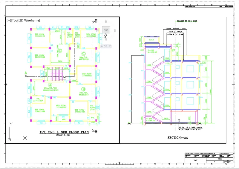
- From the Layout ribbon go to Layout Viewports Tool and click on the INSERT VIEW icon
- Click on the Plan and place in the 1st rectangle
- Similarly click on the Section and place in the 2nd rectangle
- Click on Plan view port Unlock the viewport from status bar and change scale as 1:50
- After changing scale, plan viewport boundry streched to match rectangle corners Esc
- Simlarly for the Section Viewport
- Enter MS for Model Space or click model form the status bar
- Click the Plan and pan to adjust the center of the rectangle
- Simlarly for the Section Viewport
- After that Lock the view for Plan And Section from status bar
STEP 7) LAYER COLOUR, TEXT AND DIMENSION
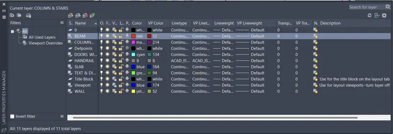
- Click the Plan view port and go to layer property change the VP (View Port) colours for different member
- Similarly for the Section Viewport
- Enter PS command for Page Layout
- Select layer as Text and Dimension
- Enter MT command for Multiline Text change text height then specify name
- Enter D for Dimension Style Manager click NEW to create Copy of Standard
- Open FIT tab change overall scale as 100 click OK then set current and close
- Enter DIMLIN command
- Specify 1st point and 2nd point to measure the distance as shown in figure
STEP 8) ATTRIBUTES
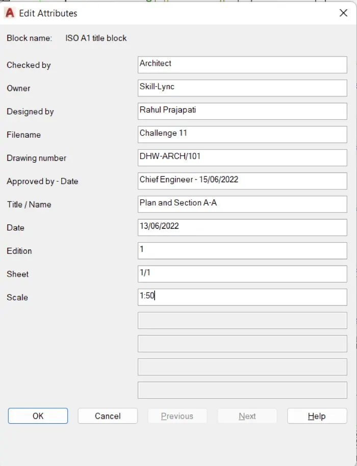
- Enter ATTEDIT command for edit attributes
- Click on the Title Block
- A dialog box of Edit Attributes shows
- Fill the required details which is necessary click OK
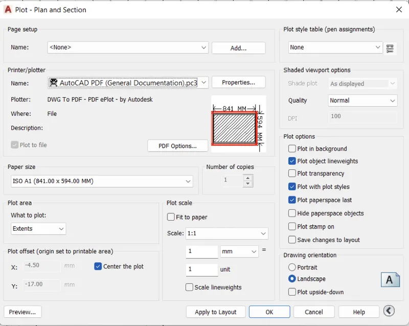
- Click on Plot icon or enter command Plot
- Ensure printer/plotter set as AUTOCAD PDF (General Documentation).pc3 click on OK
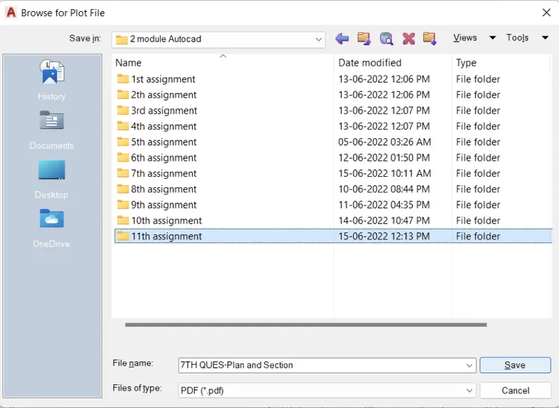
- Browse to file destination and save the PDF file
RESULT:
To follow the above procedure and obtained the final result
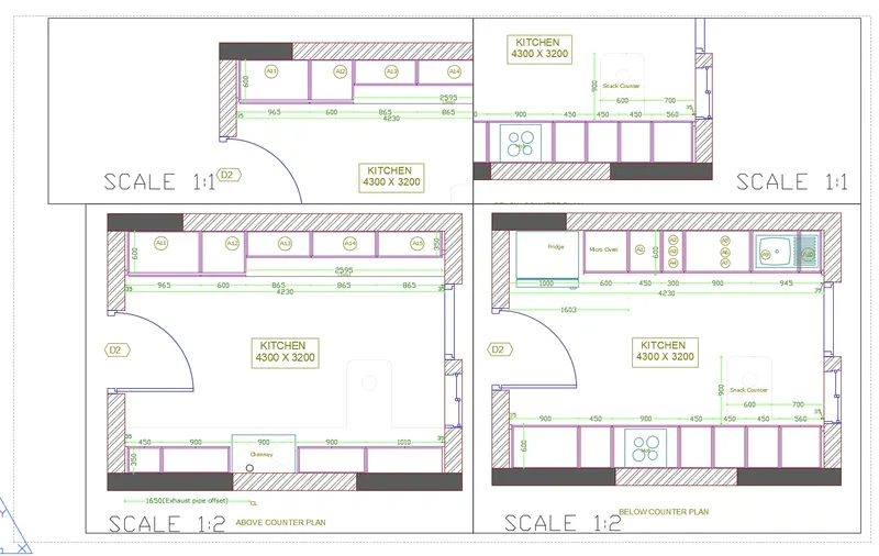
2. Create a layout of the Kitchen drawn in Challenge 9 as shown in Figure. Use the scale as shown in the Figure. Use A4 Size page for the layout. Take a plot.
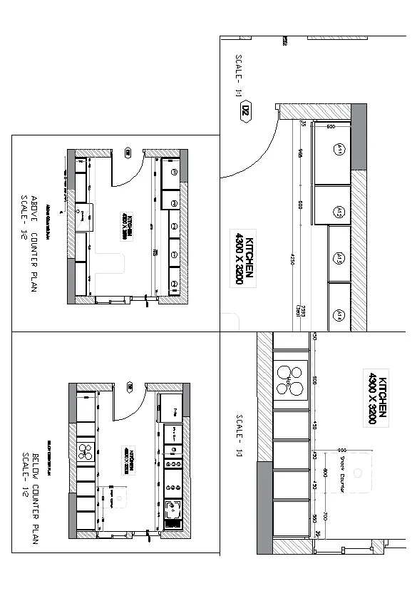
AIM: To create Kitchen layout of the challenge 9 as shown in the figure
INTRODUCTION: The Kitchen layout is created in AutoCAD. The paper size taken A4 and plot to save the PDF. Procedures explained with the diagram and the final result is given
PROCEDURE:
STEP 1) MODEL FOR DRAWING
- Open week 10 challenge in AutoCAD
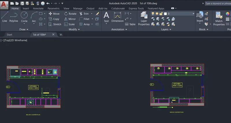
STEP 2) CREATE NEW VIEW
- Zoom the 1st part of the kitchen which is cover entire screen
- From VIEW ribbon
- In the NAMED VIEWS tool
- Click on NEW VIEW
- A dialog box is opened
- Specify View Name as Above Right Counter
- Repeat similarly for other part of the drawing
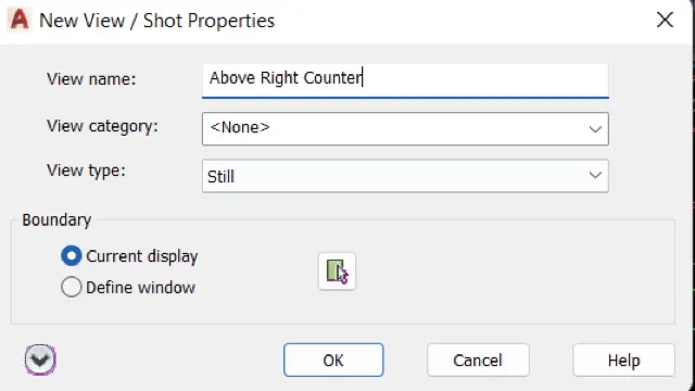
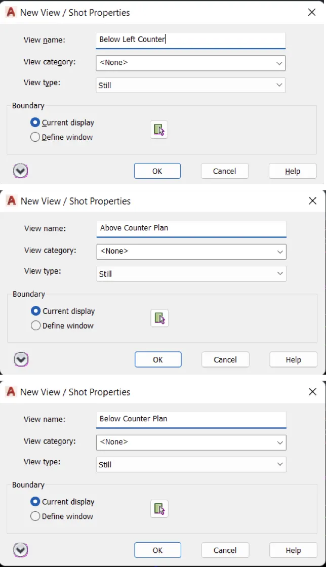
STEP 3) CREATE VIEW PORT
- In the Model Viewports Tool
- Click to drop down Viewport Configuration and select FOUR: EQUAL
- Click on the NAMED, a dialog box open as VIEWPORTS
- Go to New Viewports Tab and type new name as Kitchen Layout 1
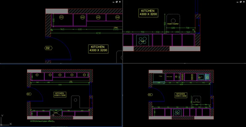
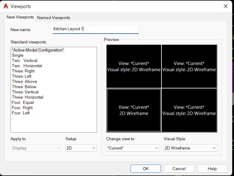
STEP 4) CREATE LAYOUT
- Enter Layout command
- Click on New option
- A model tab is added
- Right click on the new model tab to rename as Kitchen Layout
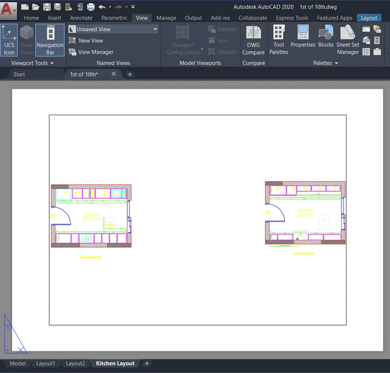
STEP 5) PAGE SETTING
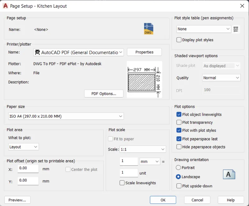
- Enter PAGESETUP command
- A dialog box shows of Page Setup Manager
- Click on Modify
- New dialog box shows of Page Setup
- Change Printer/Plotter name as AUTOCAD PDF (General Documentation).pc3
- Change page size as ISO A4 (297.00 X 210.00 MM)
- Click OK and click CLOSE
STEP 6) INSERT DRAWING
- Select to delete existing drawing in current page
- Set current layer as 0 from layer property
- From the Layout ribbon go to Layout Viewports Tool and click on the INSERT VIEW icon
- Click on the Above Right Counter and place in the sheet
- Similarly click on the other plan and place in sheet
- Resize the viewports as required
- Enter MS for Model Space or click model form the status bar
- Click the Plan and pan to adjust the viewport
- Simlarly for the other viewport
- After that Lock the viewports
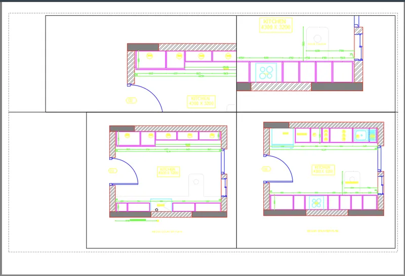
STEP 7) LAYER COLOUR and TEXT
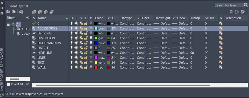
- Click the Above Right Counter view port and go to layer property change the VP (View Port) colours for different member
- Similarly for the other Viewport
- Enter PS command for Page Layout
- Enter MT command for Multiline Text change text height then specify name
STEP 8) PLOT
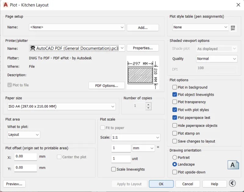
- Click on Plot icon or enter command Plot
- Ensure printer/plotter set as AUTOCAD PDF (General Documentation).pc3 click on OK
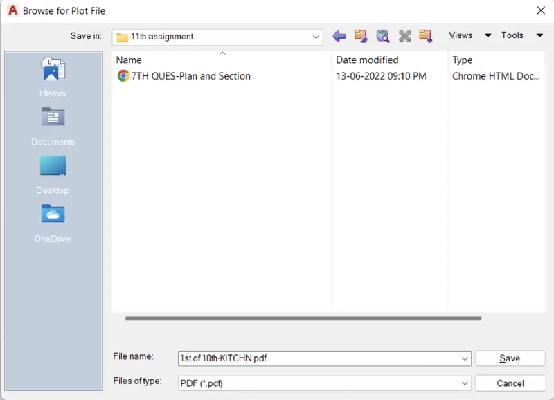
- Browse to file destination and save the PDF file
RESULT:
To follow the above procedure and obtained the final result
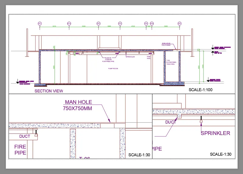
3. Create a layout of the section created in Challenges 9.
Use scale as mentioned in the Figure. Use MV command create multiple viewports. Take a plot.
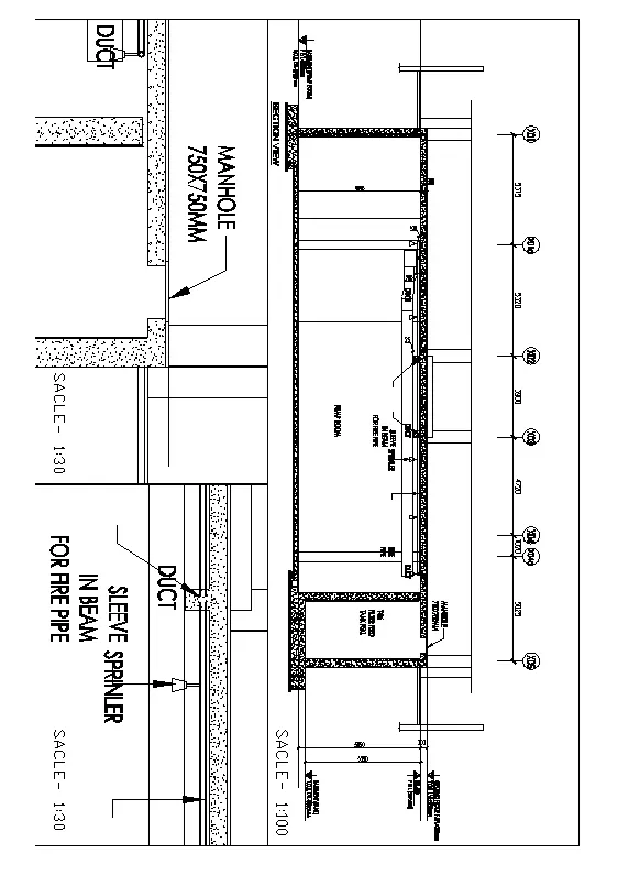
AIM: To create Kitchen layout of the challenge 9 as shown in the figure
INTRODUCTION: The Kitchen layout is created in AutoCAD. The paper size taken A4 and plot to save the PDF. Procedures explained with the diagram and the final result is given
PROCEDURE:
STEP 1) MODEL FOR DRAWING
- Open week 10 challenge in AutoCAD
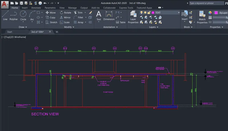
STEP 2) CREATE NEW VIEW
- Zoom the Section which is cover entire screen
- From VIEW ribbon
- In the NAMED VIEWS tool
- Click on NEW VIEW
- A dialog box is opened
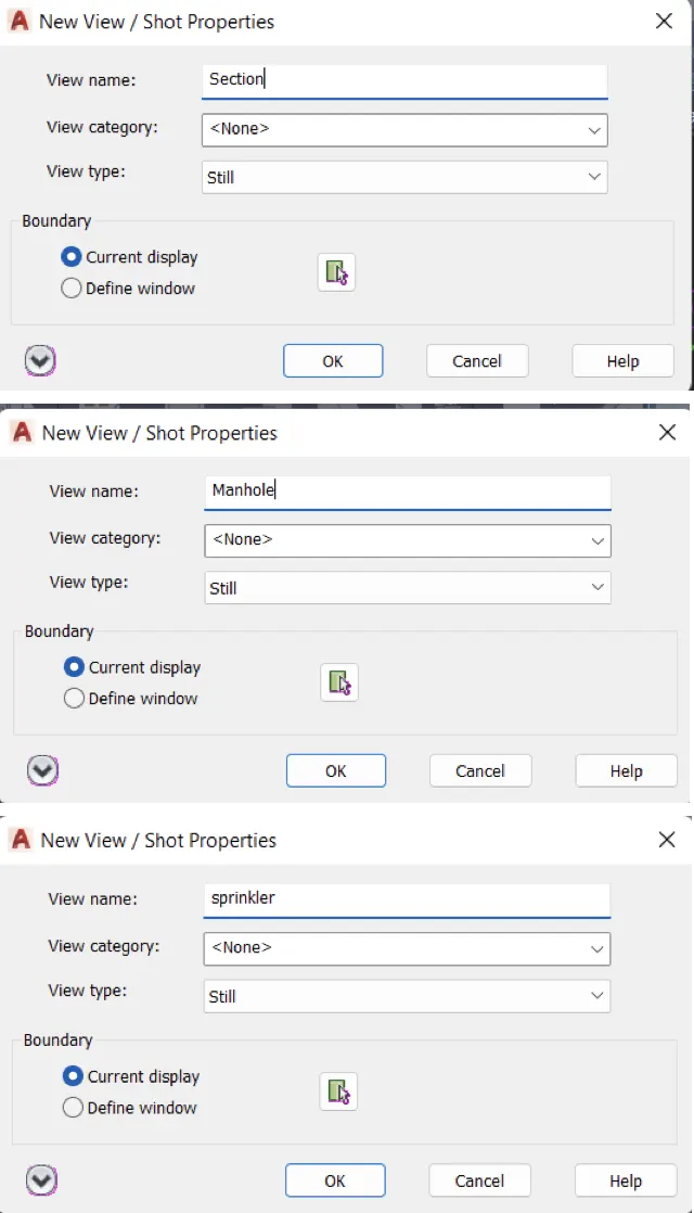
- Specify View Name as section
- Repeat similarly for other part of the drawing
STEP 3) CREATE VIEW PORT
- In the Model Viewports Tool
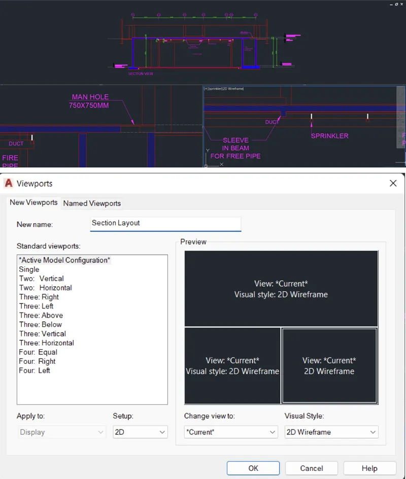
- Click to drop down Viewport Configuration and select THREE: ABOVE
- Click on the NAMED, a dialog box open as VIEWPORTS
- Go to New Viewports Tab and type new name as Section Layout
STEP 4) CREATE LAYOUT
- Enter Layout command
- Click on New option
- A model tab is added
- Right click on the new model tab to rename as Section Layout
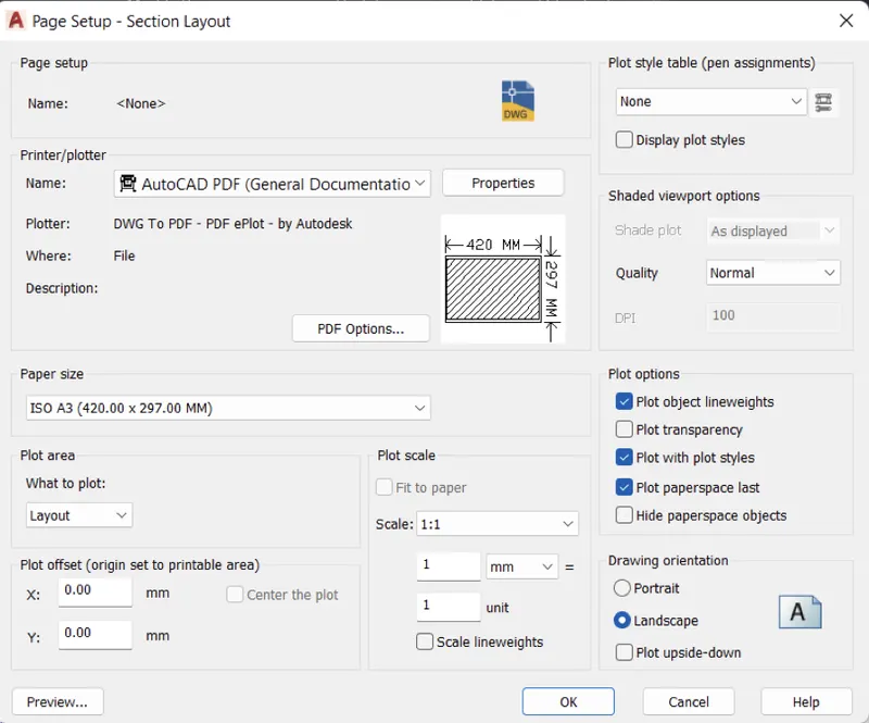
STEP 5) PAGE SETTING
- Enter PAGESETUP command
- A dialog box shows of Page Setup Manager
- Click on Modify
- New dialog box shows of Page Setup
- Change Printer/Plotter name as AUTOCAD PDF (General Documentation).pc3
- Change page size as ISO A3 (420.00 X 297.00 MM)
- Click OK and click CLOSE
STEP 6) INSERT DRAWING
- Select to delete existing drawing in current page
- Set current layer as 0 from layer property
- From the Layout ribbon go to Layout Viewports Tool and click on the INSERT VIEW icon
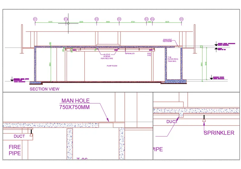
- Click on the Section and place in the sheet
- Similarly click on the Manhole and Sprinkle and place in sheet
- Click on section viewport, Unlock the viewport from status bar and change scale as 1:100
- Click on Manhole viewport, Unlock the viewport from status bar and change scale as 1:30
- Similarly for the Sprinkler viewport change the scale as 1:30
- Enter MS for Model Space or click model form the status bar
- Click the section and pan to adjust the viewport
- Simlarly for the other viewport
- After that Lock the viewports
STEP 7) LAYER COLOUR and TEXT
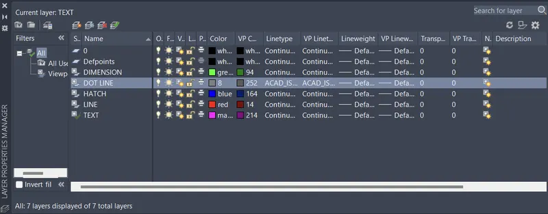
- Click the Section view port and go to layer property change the VP (View Port) colours for different member
- Similarly for the other Viewport
- Enter PS command for Page Layout
- Enter MT command for Multiline Text change text height then specify name
STEP 8) PLOT
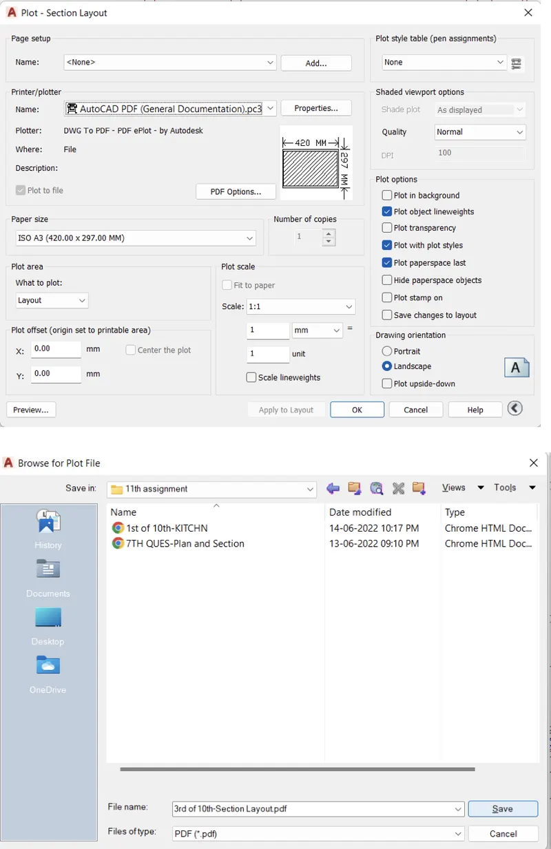
- Click on Plot icon or enter command Plot
- Ensure printer/plotter set as AUTOCAD PDF (General Documentation).pc3 click on OK
- Browse to file destination and save the PDF file
RESULT:
To follow the above procedure and obtained the final result