Creation of geometries by Coordinate system methods using AutoCad
AIM:
(A) To Create the geometries from P1 to P2 using all the coordinates system methods and P3 to P10 by any one coordinate system
(B) To Draw the profile and the trusses using any coordinate system methods. The dimensions are there for reference
Commands used:
1. Line command
2. Dimlinear command
3. Text command
4. Circle command
PROCEDURE:
Starting AutoCAD software:
- Go to START MENU, select AutoCAD 2022
- Click on START DRAWING
- In the command line type line or select from the RIBBON.
(A) To Create the geometries from P1 to P2 using all the coordinates system methods:
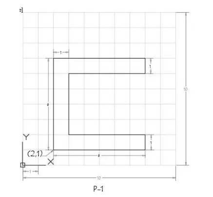
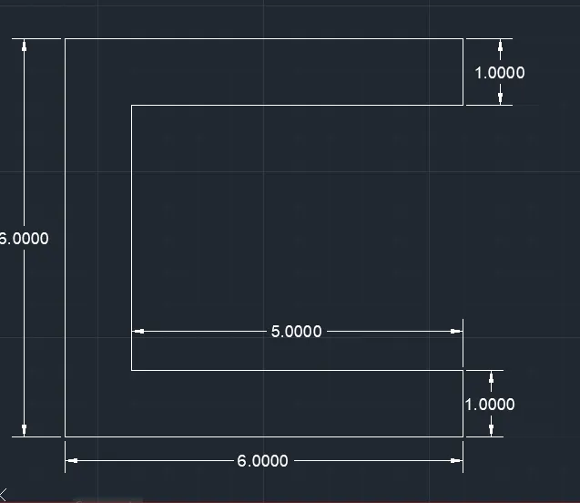
- Select the Line command
- Specify the first point as 2,1 and further specify the next points as given in the figure.
- Keep adding the point and continue with the line command.
- Then type DIM and select the dimenesions command and specify the start and end point.
- You will get the required dimensions.
PART II
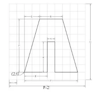
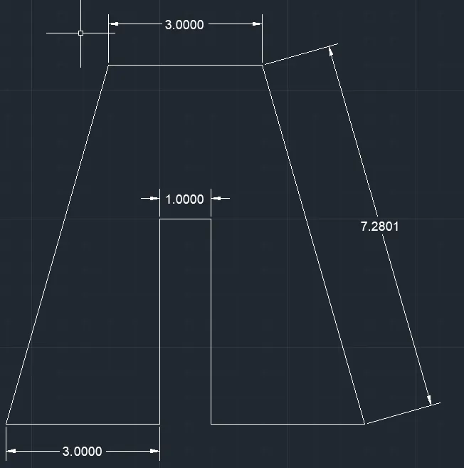
- Select the Line command
- Specify the first point as 2,1 and further specify the next points as given in the figure.
- Keep adding the point and continue with the line command.
- Then type DIM and select the dimenesions command and specify the start and end point.
- You will get the required dimensions.
PART-III
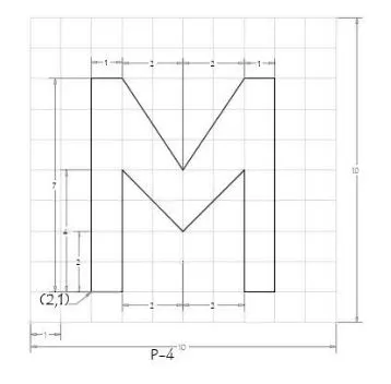
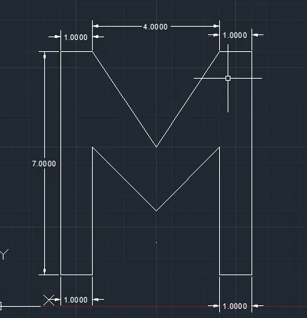
- Select the Line command
- Specify the first point as 2,1 and further specify the next points as given in the figure.
- Keep adding the point and continue with the line command.
- Then type DIM and select the dimenesions command and specify the start and end point.
- You will get the required dimensions.
PART IV
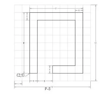
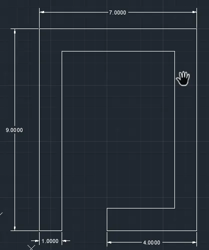
- Select the Line command
- Specify the first point as 2,1 and further specify the next points as given in the figure.
- Keep adding the point and continue with the line command.
- Then type DIM and select the dimenesions command and specify the start and end point.
- You will get the required dimensions.
PART V
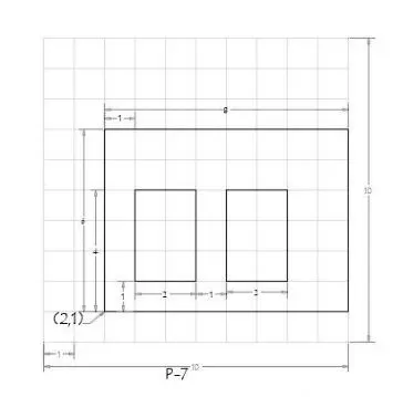
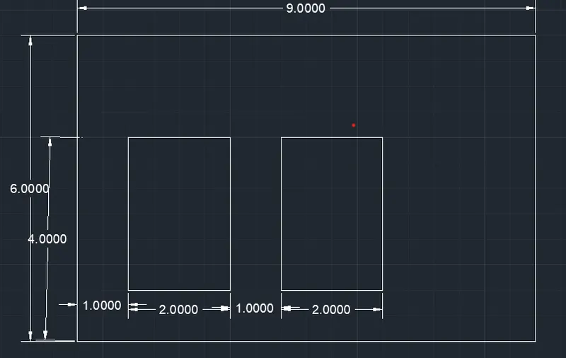
- Select the Line command
- Specify the first point as 2,1 and further specify the next points as given in the figure.
- Keep adding the point and continue with the line command.
- Then type DIM and select the dimenesions command and specify the start and end point.
- You will get the required dimensions.
PART VI
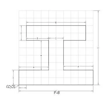
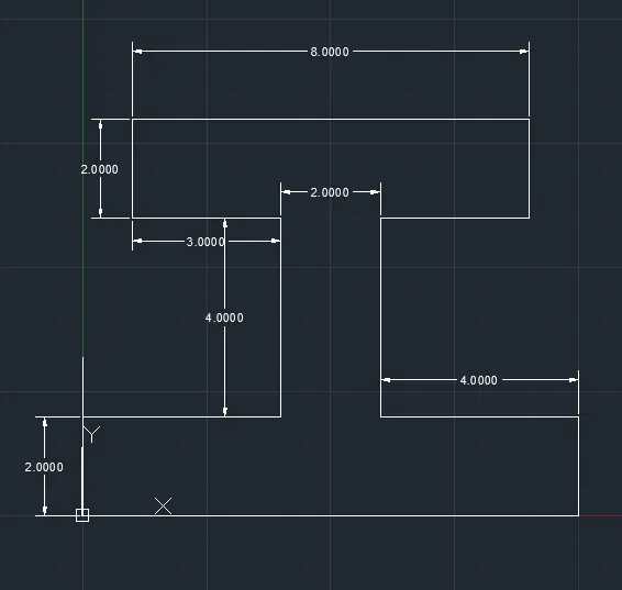
- Select the Line command
- Specify the first point as 0,0 and further specify the next points as given in the figure.
- Keep adding the point and continue with the line command.
- Then type DIM and select the dimenesions command and specify the start and end point.
- You will get the required dimensions.
PART VII
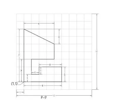
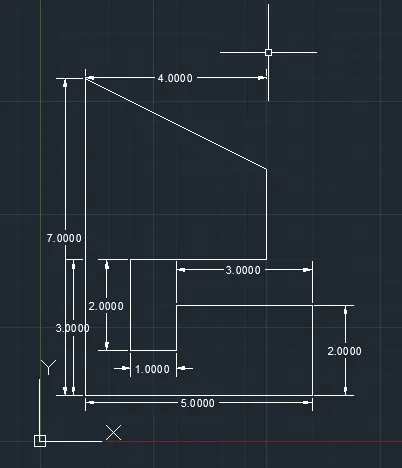
- Select the Line command
- Specify the first point as 1,1 and further specify the next points as given in the figure.
- Keep adding the point and continue with the line command.
- Then type DIM and select the dimenesions command and specify the start and end point.
- You will get the required dimensions.
PART VIII
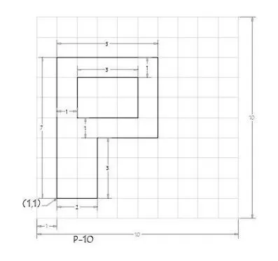
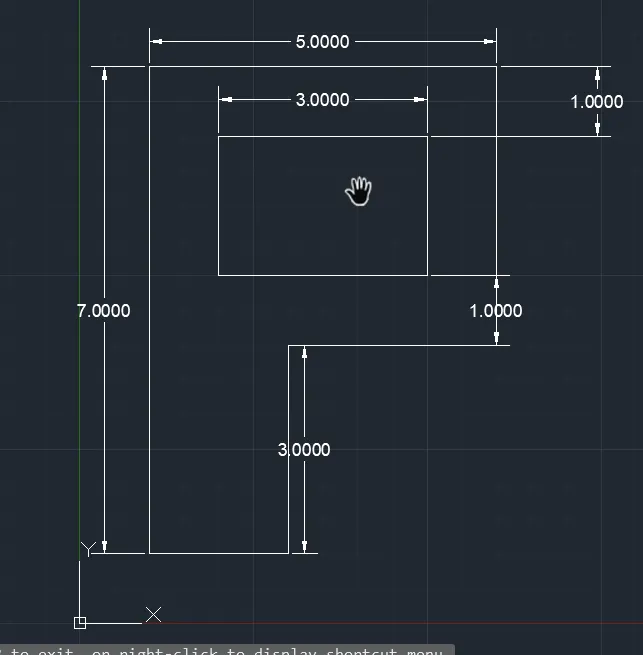
- Select the Line command
- Specify the first point as 1,1 and further specify the next points as given in the figure.
- Keep adding the point and continue with the line command.
- Then type DIM and select the dimenesions command and specify the start and end point.
- You will get the required dimensions.
PART IX
Civil Related Problems
Draw the profile and the trusses using any coordinate system methods. The dimensions are there for references.
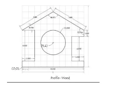
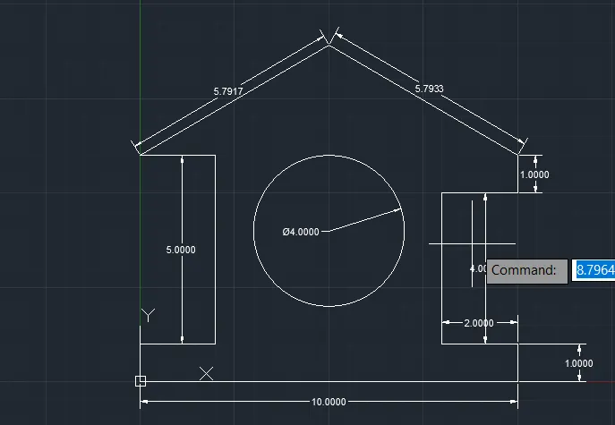
- Select the Line command
- Specify the first point as 0,0 and further specify the next points as given in the figure.
- Keep adding the point and continue with the line command.
- Then type DIM and select the dimenesions command and specify the start and end point.
- You will get the required dimensions.
PARTX
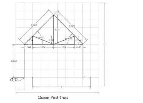
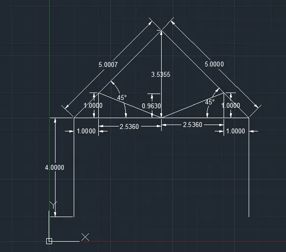
- Select the Line command
- Specify the first point as 1,1 and further specify the next points as given in the figure.
- Keep adding the point and continue with the line command.
- Then type DIM and select the dimenesions command and specify the start and end point.
- You will get the required dimensions.
PART XI
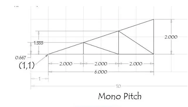
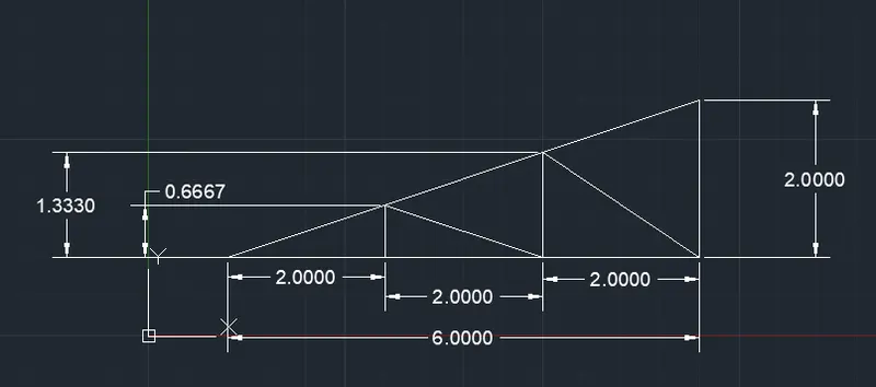
- Select the Line command
- Specify the first point as 1,1 and further specify the next points as given in the figure.
- Keep adding the point and continue with the line command.
- Then type DIM and select the dimenesions command and specify the start and end point.
- You will get the required dimensions.