Creation of geometries by Coordinate system methods using AutoCad
Aim: Creation of geometries by all Coordinate system methods using AutoCad
Procedure:
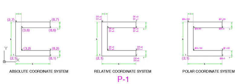
Absolute coordinate system:
- Each vertex of the geometry is given a label for identification
- The coordinates for each vertex are identified based on the given measurements
- Using the Line command in Autocad the geometry can be created by entering the coordinates(x,y) in clockwise or anticlockwise direction.
- After entering the last coordinate type close command to close the geometry to the starting point.
- Note: Dynamic Input has to be switched off.
Line
2,1
8,1
8,2
3,2
3,6
8,6
8,7
2,7
Close
Relative Coordinate system:
- Each vertex of the geometry is given a label for identification
- Each vertex can be identified with the distance in the horizontal direction as Dx and vertical direction as Dy from the previous point.
- Identify the Dx and Dy for each vertex with the given measurements in clockwise or anticlockwise direction from the previous point.
- Using the Line command enter the first vertex and further enter Dx and Dy as @Dx, Dy to reach the following points.
- In this way after reaching the last point give the command as close to close the geometry to the starting point.
Line
2,1
@6,0
@6,1
@5,0
@6,5
@0,1
@5,0
Close
Relative Polar Coordinate System:
- Each vertex of the geometry is given a label for identification
- As per the Quadrant angle system +X is considered as 0 and +Y as 90 in the anticlockwise direction by default.
- In this way the distance in x or y direction and angle from the previous point is noted for each vertex.
- Using the Line command enter the first vertex and further enter Dx or Dy as @Dx<angle or @Dy<angle to reach the following points.
- In this way after reaching the last point give the command as close to close the geometry to the starting point.
Line
2,1
@6<0
@1<90
@5<180
@5<90
@5<0
@1<90
@6<180
Close
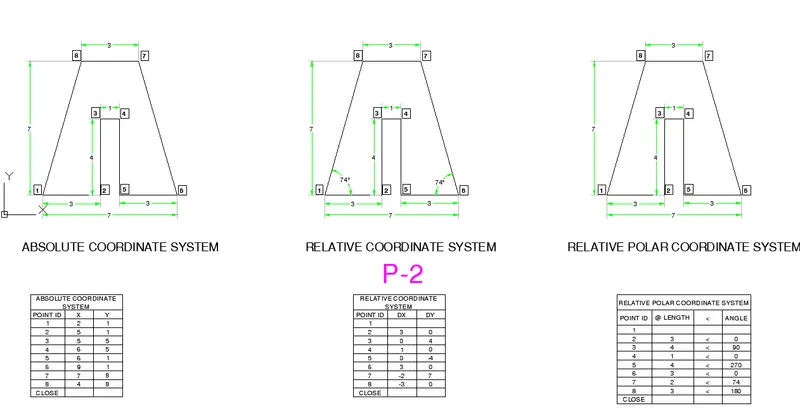
Similarly for P2:
Absolute coordinate system:
Line
2,1
5,1
5,5
6,5
6,1
9,1
7,8
4,8
Close
Relative coordinate system:
Line
2,1
@3,0
@0,4
@1,0
@0,-4
@3,0
@-2,7
@-3,0
Close
Relative Polar coordinate system:
2,1
@3<0
@4<90
@1<0
@4>270
@3<0
@2<74
@3<180
Close
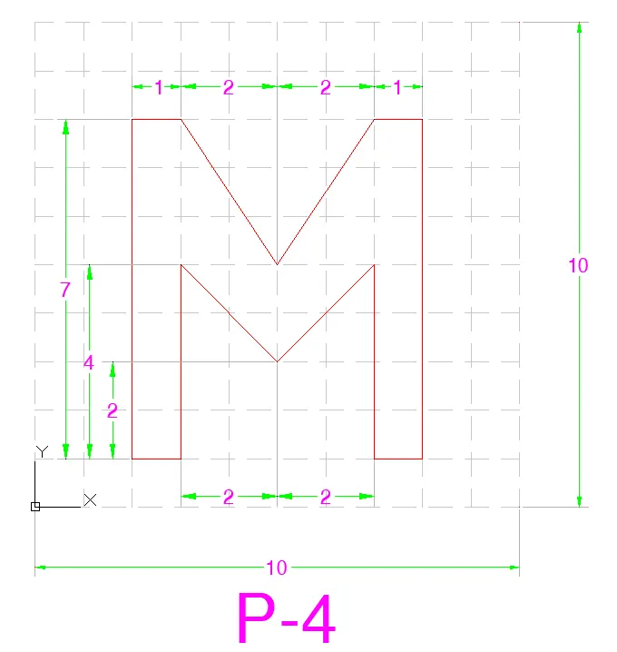
P4
Line
| 2,1 |
| 2,8 |
| 3,8 |
| 5,5 |
| 7,8 |
| 8,8 |
| 8,1 |
| 7,1 |
| 7,5 |
| 5,3 |
| 3,5 |
| 3,1 |
Close
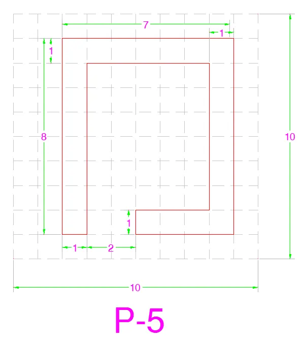
P5
Line
| 2,1 |
| 3,1 |
| 3,8 |
| 8,8 |
| 8,2 |
| 5,2 |
| 5,1 |
| 9,1 |
| 9,9 |
|
2,9 |
Close
P7
| Line |
| 2,1 |
| 2,7 |
| 10,7 |
| 10,1 |
| Close |
| Line |
| 3,2 |
| 5,2 |
| 5,5 |
| 3,5 |
| 3,2 |
| Close |
| Line |
| 6,2 |
| 6,5 |
| 8,5 |
| 8,2 |
| 6,2 |
| Close |
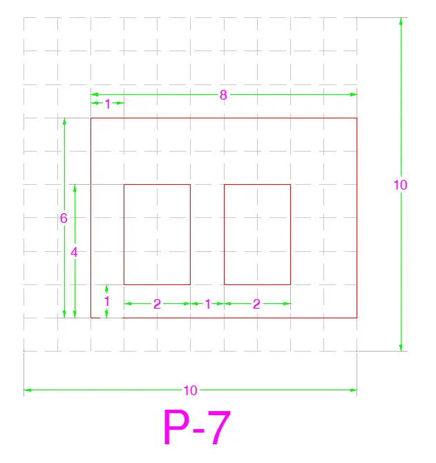
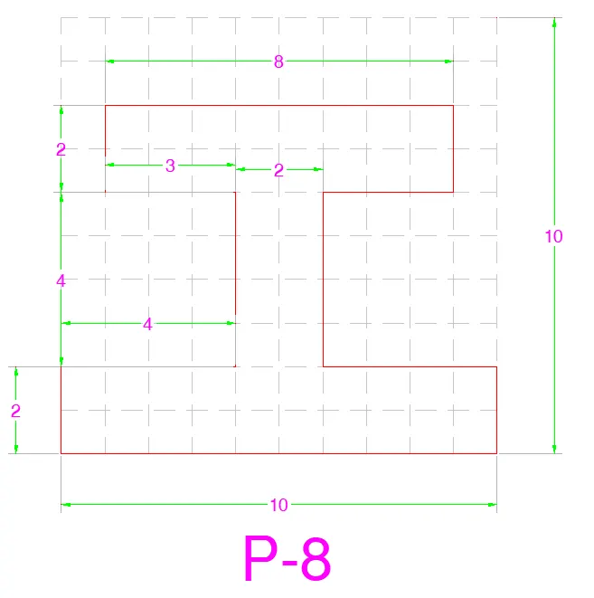
P8
| Line |
| 0,0 |
| 0,2 |
| 4,2 |
| 4,6 |
| 1,6 |
| 1,8 |
| 9,8 |
| 9,6 |
| 6,6 |
| 6,2 |
| 10,2 |
| 10,0 |
| Close |
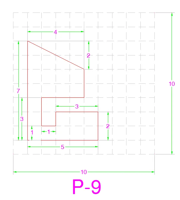
P9
| Line |
| 6,3 |
| 6,1 |
| 1,1 |
| 1,8 |
| 5,6 |
| 5,4 |
| 2,4 |
| 2,2 |
| 3,2 |
| 3,3 |
| Close |
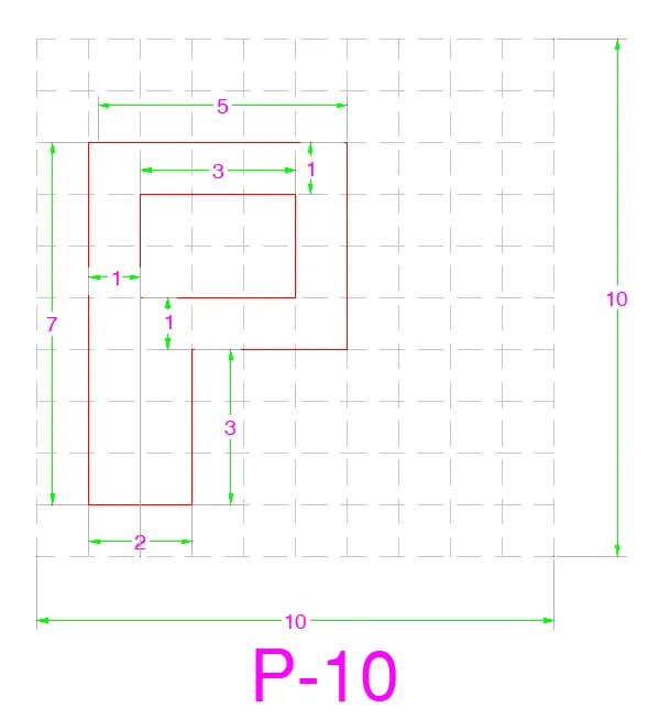
P10
| Line |
| 1,8 |
| 6,8 |
| 6,4 |
| 3,4 |
| 3,1 |
| 1,1 |
| Close |
| Line |
| 5,7 |
| 5,5 |
| 2,5 |
| 2,7 |
| Close |
Civil Related Problems
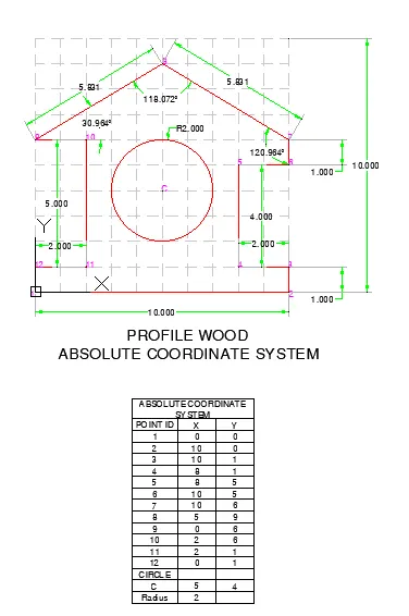
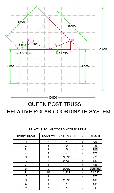
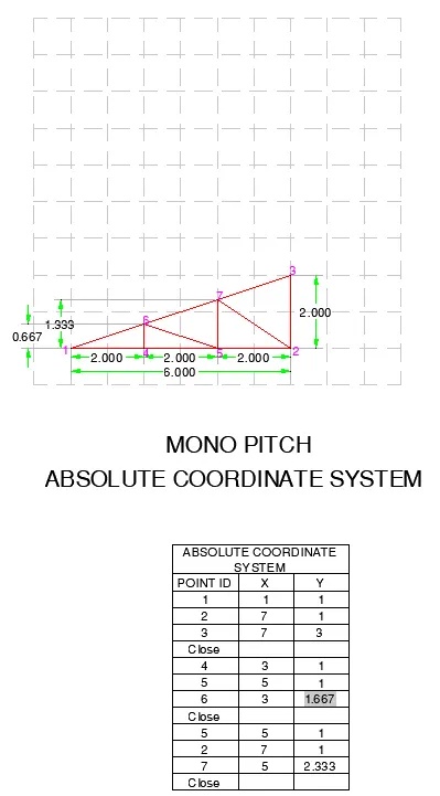
Draw the profile and the trusses using any coordinate system methods. The dimensions are there for references.
Profile wood
Absolute coordinate system:
| Line |
| 10,6 |
| 5,9 |
| 0,6 |
| 2,6 |
| 2,1 |
| 0,1 |
| 0,0 |
| 10,0 |
| 10,1 |
| 8,1 |
| 8,5 |
| 10,5 |
| Close |
|
Circle |
| 5,4 |
| Radius -2 |
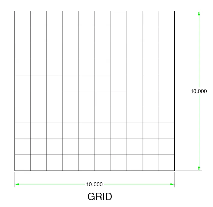
| Line |
| 0,0 |
| 0,10 |
| Line |
| 1,0 |
| 1,10 |
| Close |
| Line |
| 2,0 |
| 2,10 |
| Close |
| Line |
| 3,0 |
| 3,10 |
| Close |
| Line |
| 4,0 |
| 4,10 |
| Close |
| Line |
| 5,0 |
| 5,10 |
| Close |
| Line |
| 6,0 |
| 6,10 |
| Close |
| Line |
| 7,0 |
| 7,10 |
| Close |
| Line |
| 8,0 |
| 8,10 |
| Close |
| Line |
| 9,0 |
| 9,10 |
| Close |
| Line |
| 10,0 |
| 10,10 |
| Close |
| Line |
| 0,0 |
| 10,0 |
| Close |
| Line |
| 0,1 |
| 10,1 |
| Close |
| Line |
| 0,2 |
| 10,2 |
| Close |
| Line |
| 0,3 |
| 10,3 |
| Close |
| Line |
| 0,4 |
| 10,4 |
| Close |
| Line |
| 0,5 |
| 10,5 |
| Close |
| Line |
| 0,6 |
| 10,6 |
| Close |
| Line |
| 0,7 |
| 10,7 |
| Close |
| Line |
| 0,8 |
| 10,8 |
| Close |
| Line |
| 0,9 |
| 10,9 |
| Close |
| Line |
| 0,10 |
| 10,10 |
| close |