Creating a Floor plan, Footing detail and Isometric view using AutoCad
Aim: Cross Section of Load Bearing Wall showing foundation details
Procedure: As per the given drawing, the following step by step commands are used to create the drawing
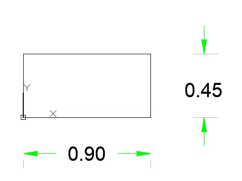
- Command "Rec" - draws a rectangle
- Input starting point as 0,0 and the next point is given dimension as @0.9,0.45 - this completes the rectangle in the bottom
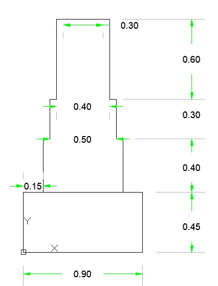
- Draw a Polyline vertical and horizontal lines with ortho on up to 3 steps of the foundation
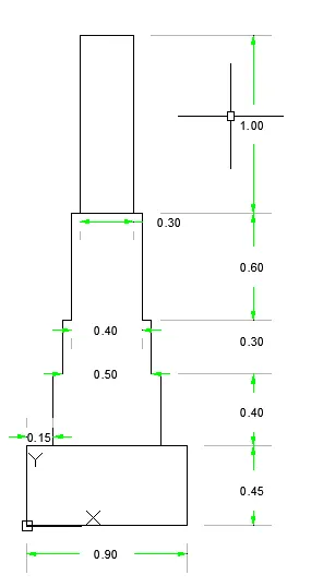
- Draw a rec of dimension @0.3,1 from 0.05 offset of last step of foundation to complete the drawing.
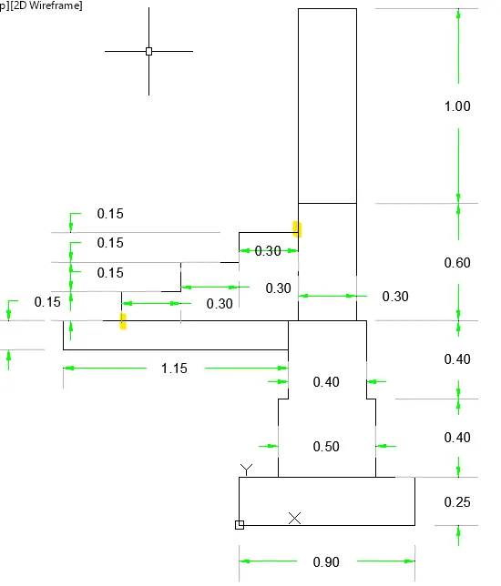
Aim: C.S. OF LOAD BEARING WALL OVER SPREAD FOOTING
Procedure:
- Command "Rec" - draws a rectangle
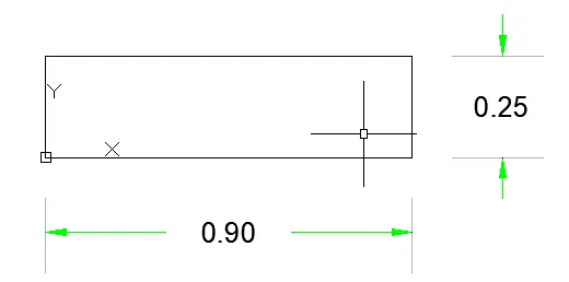
- Input starting point as 0,0 and the next point is given dimension as @0.90,0.25 - this completes the rectangle in the bottom
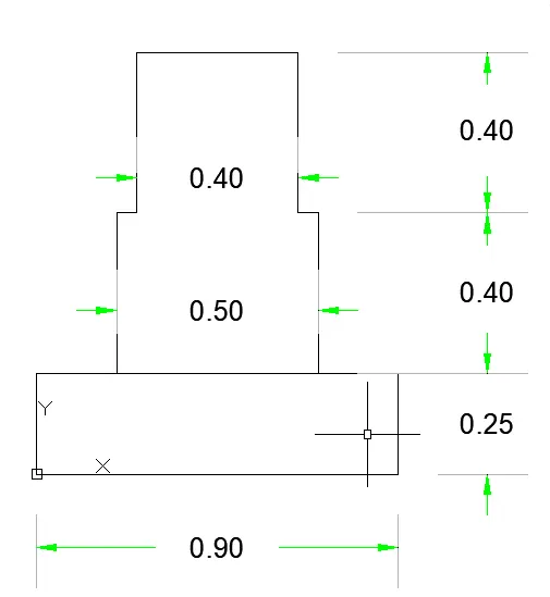
- Draw a Polyline vertical and horizontal lines with ortho on up to 3 steps of the foundation
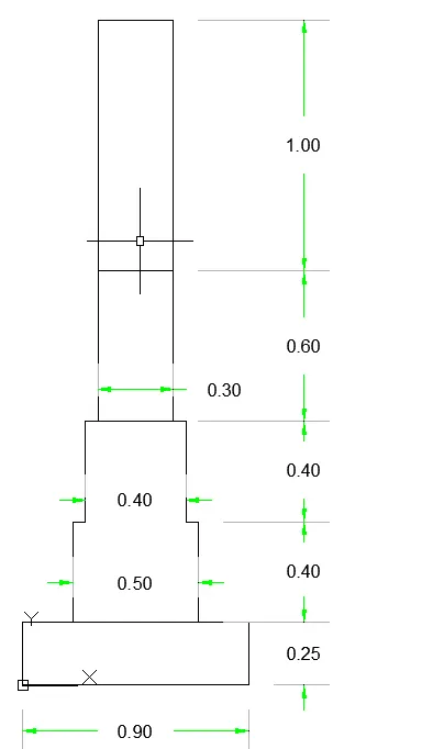
- Draw the rec from last step of foundation of offset 0.05 inner @0.3,0.6 dimensions
- Over this draw a rectangle @0.3,1 of dimensions.
- Coming over to the steps of rise 0.15 and tread 0.30
- Draw a Rectangle of @1.15, 0.15 from the shown corner
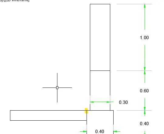
- Draw a polyline of 0.15 vertical and 0.30 horizontal alternatively 3 times towards the right side to meet the rectangle @0.3,0.6 from the offset 0.30 at the end of the above drawn rectanlge as shown
Aim: C.S. ISOLATED FOOTING
Procedure:
AS drawing is symmetric at centre, half of the drawing to the left side is drawn and mirrored to the right side
Command Polyline is used to start the drawing at the center of the footing bottom.
Pl
@0.5<180
@0.15<90
@0.38,0.25
@1.6<90
@0.12<0
Enter
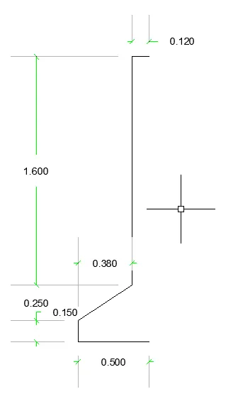
Mirror the drawnline to the right side using Mi command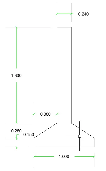
Draw a line 1.96 m length from the top of the footing end leaving am offset of 0.04.
@0.38<180
@0.05<90
Enter
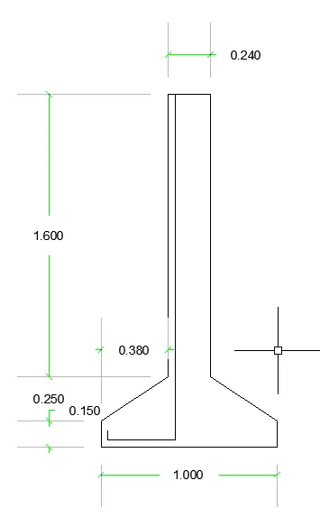
Mirror the line to the right
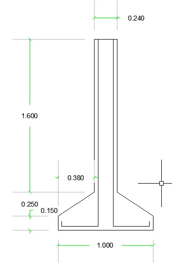
Join the two lines at the top using Line command
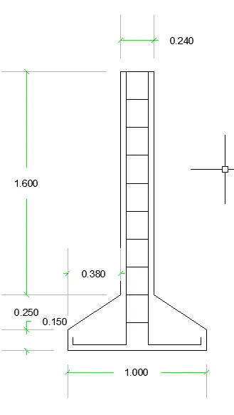
offset the line with 0.20 to the below up to the end of the footing.
Result:
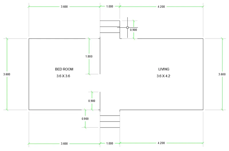
LINE DIAGRAM OF A TWO BEDROOM BUILDING
PL
@0.90<270
@3.60<180
@3.60<90
@3.6<0
@0.90<90
@1<0
@0.9<270
@4.2<0
@3.6<270
@4.20<180
@0.9<270
@1<180
@0.9<90
Close
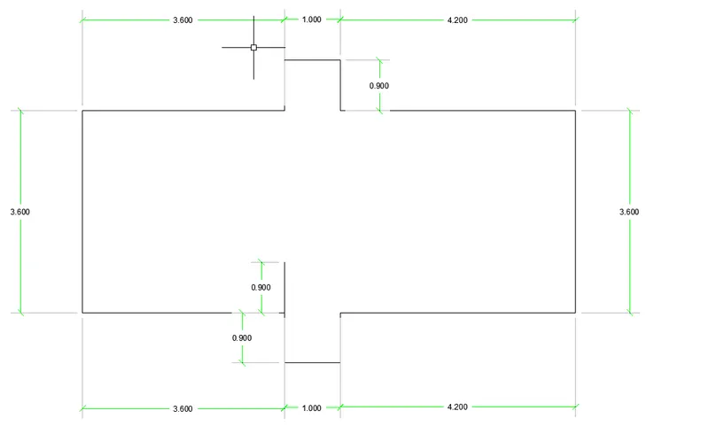
copy the Line 1m length of steps to above 0.3 m distance
Copy
Selct the line
select base point as end
copy to 0.30 & 0.60 above two times
Simillarly on the other side
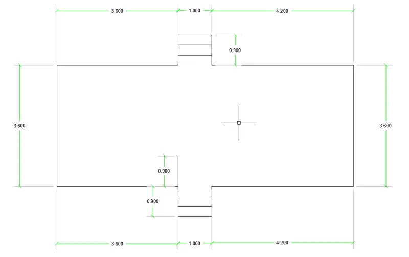
Draw a line of 1.8m length from the steps of the other side
Result
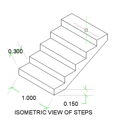
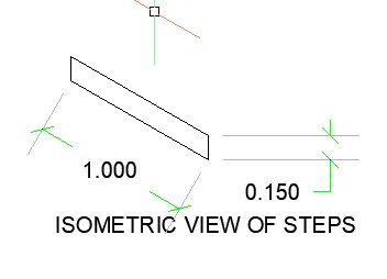
ISOMETRIC VIEW OF STEPS
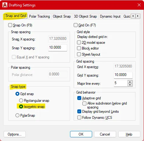
Open Drafting settings
Snap and Grid settings
under snap type
Select Isometric snap
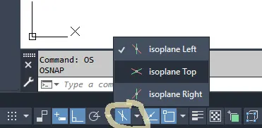
In Isoplane left
Draw Pline 1,0.15 closed rectangle.
Change the axis to Isoplane Top
Draw Pline 1,0.30 closed rectangle.
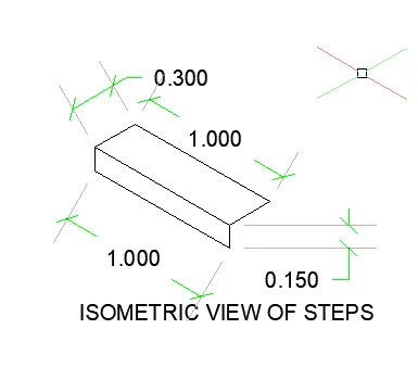
Copy these lines from base point as left most corner and place over the top left corner for four times to create five steps.
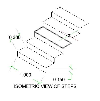
Draw a line of 0.30 towards +X from the right bottom corner
and Draw a line of 0.15 towards -Z from the top right corner
Join these lines to get the result.