Creating a Residence Layout, Seating plan, Toilet and Utility room plan using AutoCad
- Residence Plan:
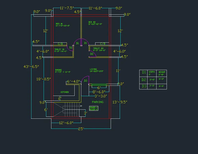
Sketch the layout of a residence as shown in the Figure 1. Consider all dimensions as reference to sketch the unit plan. Also the text in the layout are only for reference. Assume the missing dimensions. Also, refer the schedule for size of the doors.
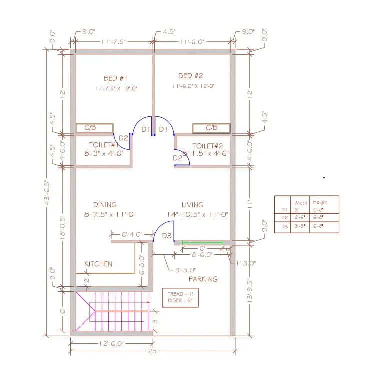
Aim:
To sketch the layout of residence using AutoCAD software using engineering unit as the drawing units.
Introduction :
Various command used while Sketching :
- Line command
- Unit command
- Lim max command
- XL command
- Zoom command
- Arc command
- Trim command
- Text command
- Extent command
- Fillet command
- Rectangle command
- Circle command
- Copy command
- LT command
- Dimension command
- Layer command
- Offset command
- Limits command
PRODUCTRE :
STEP 1 :
- GO to START MENU ,select AutoCAD 2018.
- Enter “UNITS” command in the command tab.
- Open “ Drawing units “ dialogue box , Type as “ENGINEERING” and precision as 00
- Then click units scale to “ INCHES”
- Click “OK”.
- Enter “ LIM MAX” command in the command tab.
- Enter new value for Lim max as 100’,100’.
- Enter “zoom” command in the command box.
- Enter “All” command in the command box.
- Enter “LIMITS” command in the command box.
- Specify lower left corner as
- Enter “zoom “ command in the command box.
- Enter “ALL” command in the command box.
Step 2:
- Enter “XL “ (OR) “ X line” command in the command box.
- Specific a point as “Vertical” command in the command box.
- Move the line to somewhere , where you want
- Than click “ESC” command in the command box.
- Enter “XL “ (OR) “ X line” command in the command box.
- Specific a point as “Horizontal” command in the command box.
- Move the horizontal line to close to the vertical line.
- Than click “ESC” command in the command box.
- Enter “Offset” command in the command box.
- Select the “VERTICAL” line and give a specific point as 25” from the previse vertical line.
- Click “ENTER”.
- Than click “ESC” command in the command box.
- Enter “Offset” command in the command box.
- Select the “Horizontal” line and give a specific point as 43’-6.5”.
- Click “ENTER”.
- Than click “ESC” command in the command box.
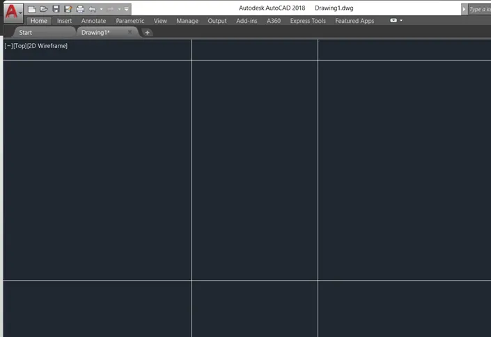
- Enter “TRIM” command in the command box
- Select the lines ,Trimmed extra lines around the box.
- Create like a box.
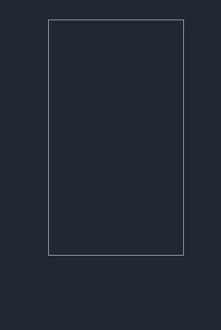
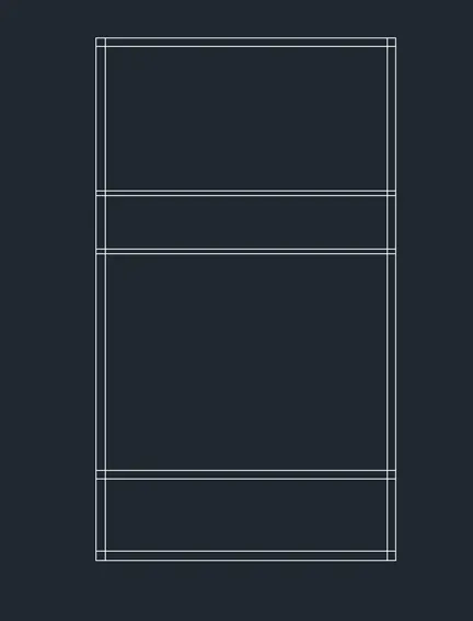
- Enter “ offset “ command in the command box.
- Select the “Horizontal “
- Create a main wall made of thickness 0”
- Enter “ offset “ command in the command box.
- Select the “Vertical “
- Create a main wall made of thickness 0”
- this all wall are will coming up inside of box.
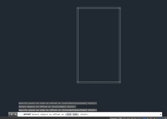
RISER :
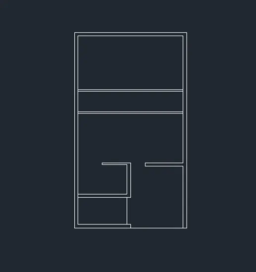
- Enter “Offset” command in the command box.
- Create “Riser “for 6’ from the wall
- Select the line , and
- Then click “ESC”.
- Enter “offset” command in the command box.
- Create a internal wall size of 0”
- Select the line and ENTER.
- Than click “ESC”.
DINNING AND KITECH :
- Enter “offset” command in the command box.
- Create “KITCHEN “ and “DINNING” size of 18’-0.5”
- Select the line from the internal wall.
- Click “Enter”
- Than click “ESC”.
- Enter “offset” command in the command box.
- Create a internal wall size of 5”
- Select the line and ENTER.
- Than click “ESC”.
- Enter “offset” command in the command box.
- Specific point of the size of 12’-6.0” , from the main wall “RISER” “KITCHEN “and “DINING”
- Select the line and
- Than click “ESC”.
- Enter “Offset” command in the command box.
- Specific point of the size of 0”
- From the centre line.
- Enter “Trim” command in the command box.
- Trimmed extra line
- Than Click “Esc”
- Enter “ fillet” command in the command box.
- Joint the wall
TOILET #1
- Create a “Toilet #1 ” room size of 4’-6.0”
- Select the line and
- Than click “ESC”.
- Enter “offset” command in the command box.
- Create a internal wall size of 5”
- Select the line and
- Than click “ESC”.
BED ROOM #1
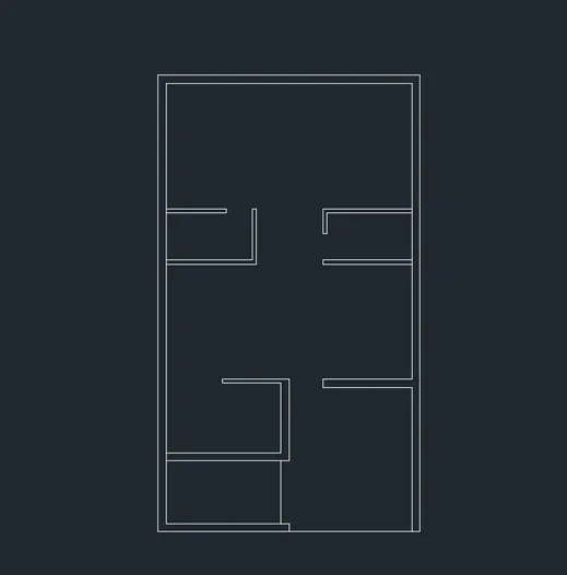
- Enter “OFFSET” command in the command box.
- Specific value of the size is 11’-7.5”
- Click “ENTER” and “close”.
- Than create wall between Bed #1 and Bed #2
- size of the wall is 5”
- Enter “TRIM” command in the command box.
- Trimmed extra lines .
BED ROOM #2
- Enter “Offset “ command in the command box.
- Click horizontal line form the main in top
- Give specific value of the size is 12’-0”
- Click “Enter” and close .
- ESC
TOILET #2
- Create a “Toilet #1 ” room size of 4’-6.0”
- Select the line and
- Than click “ESC”.
- Enter “offset” command in the command box.
- Create a internal wall size of 5”
- Select the line and
- Than click “ESC”.
- Enter “offset “ command in the command box.
- Specific value of the size is 8’-1.5” for “Toilet” length
- Enter “offset” command in the command box.
- Create a internal wall size of 5”
- Enter “TRIM “ command in the command box.
- Trimmed extra lines
- Use fillet
- Use “fillet” command to joint the wall.
LIVING :
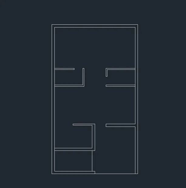
- Enter “Offset” command in the command box.
- Specific value of the size is 14’-1.05” from the internal wall for toilet
- Click “ENTER” and “ESC”.
- Create internal wall for living room
- Enter “Offset” command in the command box.
- Specific value of the size is 0” for inter wall
- Click “ENTER” and “ESC”.
DOORS:
- Trim all the door openings with their respective width D1-3” , D2 -2.6” , D3-3.3”
- Go to the “HOME” tap
- Click “ ARC” tap .
- Click “START,END, DIRECTION”. Create a door as per the drawing.
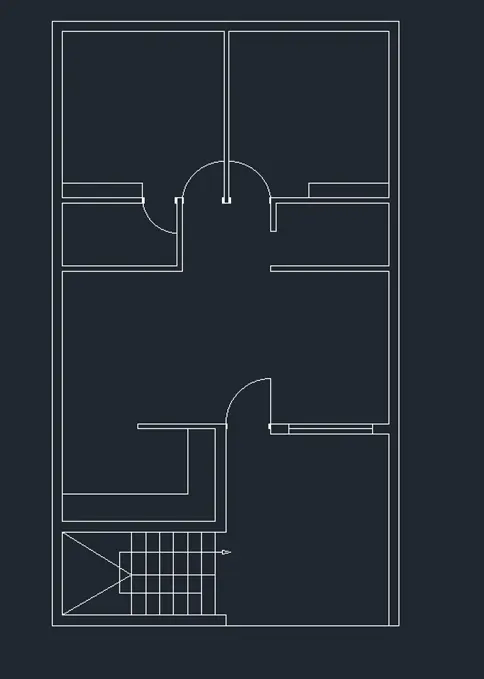
Stairs case :
- Given: thread: 1'
- riser: 6"
- Give a wall thickness of 9" for the staircase room.
- Divide the staircase room by giving offset of 3' from the front wall thickness.
- Give an offset of 96" to show the handrail (Assume ,5cm is usually given)
- Draw offset of 1'(thread) to draw the stairs in plain view.
- Draw 9 offsets as there are 9 risers for 8
- Trim of the lines between the handrails and give the other side as dotted lines (it indicates that it is the upward stairs, not visible when viewing ground floor plan)
- For that select the lines and change the line type to ISO dash.
- Mark the direction of stairs.
WINDOW:
- Create window individually
- Enter “LINE” command in the command box.
- Give specific value size 6’ horizontally
- Give thickness value size is 0”
- Click “ENTER” and
- Give centre line in mid point.
- Enter “move “ command in command box.
- Click base point of the window.
- Move it to living and parking “find the midpoint of the wall and fixed
SLAB AND CUPBOARD
- Enter “Offset” command in the command box.
- Specific value of size is 2’ give horizontally and vertically from the internal wall of “KITCHEN”
- Enter “ TRIM” command in the command box.
- Trimmed extra line.
- ESC.
TEXT , DIMLINER , AND LAYOUR COLOUR
- Enter “D” command in the command box.
- Go to the modify tap.
- Enter the “ARROW SIZE AS 1’ and “TEXT HEIGHT AS 1’
- Click “SET CURRENT”
- Than click “OK”
- Enter “DIMLINER” command in the command box.
- Show the measurement size of the “ TOILET , UTILITY “WINDOW AND DOORS”.
- Enter “TEXT” command in the command box.
- Click the specify point as inside of the room
- Give a Text height as 1’ and give angle as 0
- Than type the room name and dimension
Click “ENTER” and enter “ESC”.
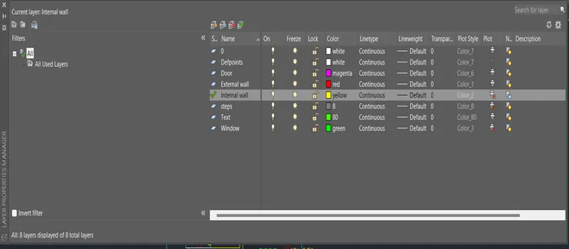
- Go to the “HOME” tap and click “layer properties”
- Create a new layer as per your requirement
- Change the “Layer name “ and “Layer colour”.
- Ex: external layer, Internal layer , Text, Window, Stairs case, ect,.
- Apply the layers in your drawing .
RESULT:
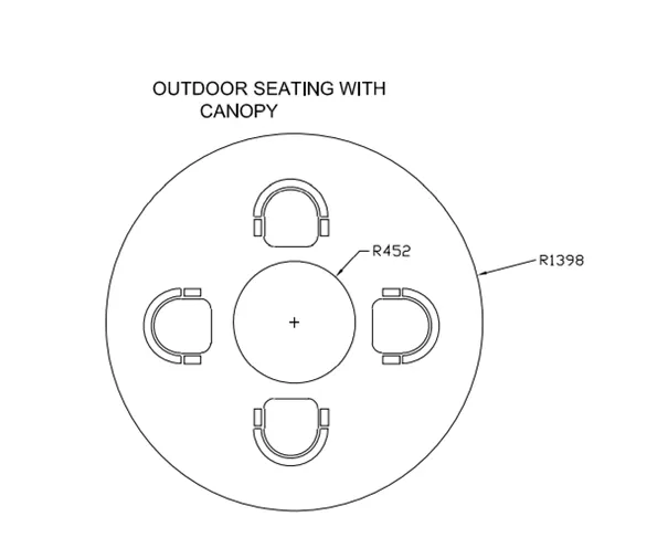
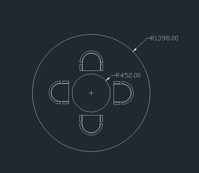
- Sketch the seating plan for an outdoor canopy. Assume the dimensions for the seating. Also, consider the dimensions in mm.
AIM:
To draw the seating plan for canopy.
Introduction :
Various command used while Sketching :
- Circle
- Offset
- Fillet
PROCEDURE:
Creating circles:
STEP 1:
- GO to START MENU ,select AutoCAD 2018.
- Enter “UNITS” command in the command tab.
- Open “ Drawing units “ dialogue box , Type as “DECIMAL” and precision as 00
- Then click units scale to “ MILL METER”
- Click “OK”.
- Enter “Limits” command in the command box.
- In the command prompt “select Off”
- Click “Enter”
- Select “Home” Select “ CENTRE ,RADIUS”.
- Specify centre point of the circle 0,0
- Specify radius of the circle is 1398 mm
- Click “Enter”.
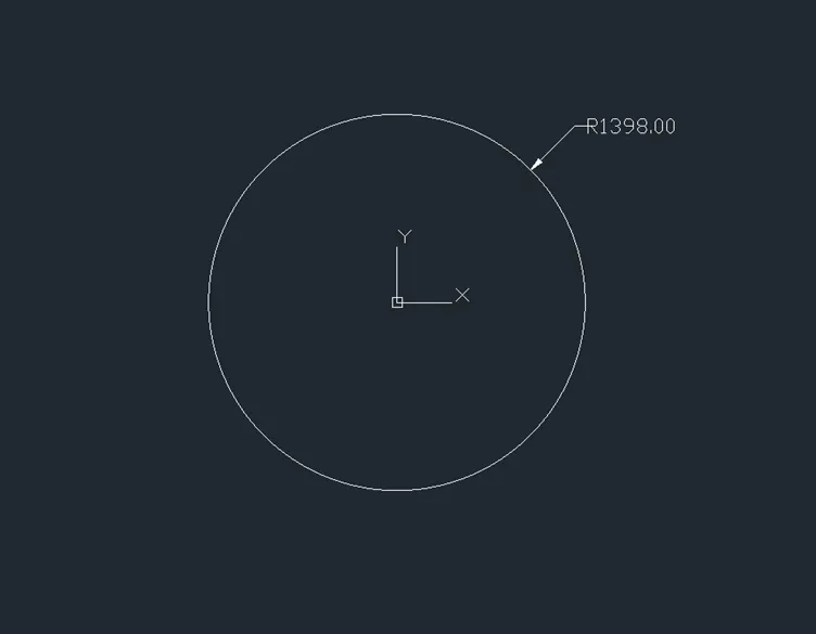
STEP :2
- Select “Home” tap. Select “ CENTRE ,RADIUS”.
- Specify centre point of the circle 0,0
- Specify radius of the circle is 452 mm
- Click “Enter”.
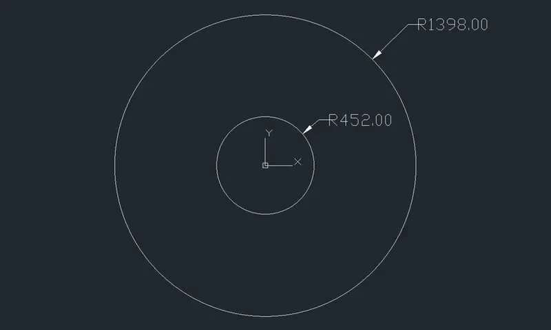
STEP :3
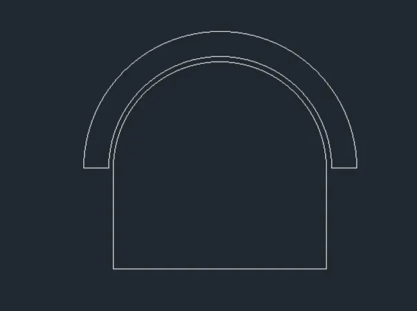
- To create a chair follow the steps below :
- Enter “Line” command in the command box.
- Draw the horizontal line of length 424mm
- Draw vertical line length of 200mm from starting and end point previously created in positive “Y”
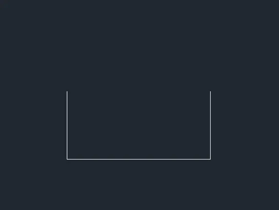
- Select home tap , Select “ARC” command .
- From the drop down list , select “Start, End, Direction”.
- Select the start and end point from the end previously created line.
- Select the direction according to requirement.
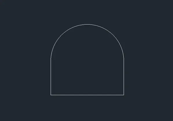
- Enter “Offset “ command in the command box.
- Enter the distance as 10 mm and select the previously created “ARC”.
- Click “ESC”.
- Enter “Offset “ command in the command box.
- Enter the distance as 50 mm and select the previously created “ARC”.
- Join the ends of “ARC” using “LINE” command .
- Select “REC” command in command box.
- Draw two RECTANGALE of same assumed size and align them properly.
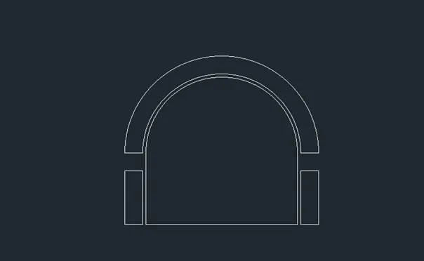
Step 4:
- Place the created chairs inside 1392 mm radius circle. Align it properly according to the sketch.
- Enter “ARRAY” command in the command box.
- Select the objects created in the previous step.
- Select the path as 452mm radius circle.
- Adjust the direction such that required are created as per the requirement
RESULT:
- Sketch the part plan for the toilers and utilities room. Consider the outer wall thickness as 300mm and inner wall thickness as 150mm. Also, assume the missing dimension, Texts, dimensions, and hatches are only for references. Also, symbols for toilets and w/c are also for references.
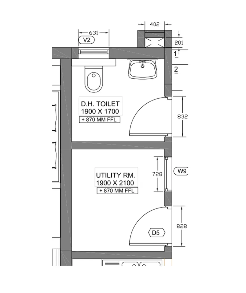
AIM:
To Sketch the part plan for the TOILER and Utilities room using AutoCAD.
PROCEDURE:
Various command used while Sketching :
- Line command
- Unit command
- Lim max command
- XL command
- Zoom command
- Arc command
- Trim command
- Text command
- Extent command
- Fillet command
- Rectangle command
- Circle command
- Copy command
- LT command
- Dimension command
- Layer command
- Offset command
- Limits command
STEP 1 :
- GO to START MENU ,select AutoCAD 2018.
- Enter “UNITS” command in the command tab.
- Open “ Drawing units “ dialogue box , Type as “MILLI METER” and precision as 00
- Then click units scale to “ DECIMAL”
- Click “OK”.
- Enter “LIMITS” command in the command box.
- In the command prompt , Select “Off”.
- Click “ENTER”.
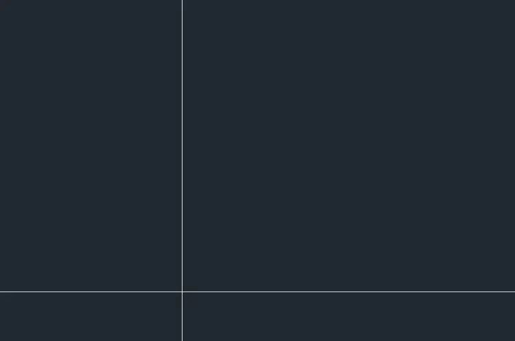
- Enter “XLINE” command in the command box.
- Enter “vertical” command in the command box.
- Place “XLINE” in the command prompt and press enter.
- Enter “XLINE” command in the command box.
- Enter “HORIZONTAL” command in the command box.
- Place the “XLINE” in the workspace such that it forms the corner point .
- Click “ESC”.
STEP 2:
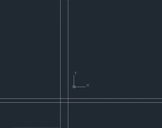
- Enter “OFFSET” command in the command box.
- Enter the offset distance as 300mm in the command box.
- Select the vertical “XLINE” and click by keeping the cursor on right side .
- Click “ESC”.
- Enter “OFFSET” command in the command box.
- Enter the offset distance as 150mm in the command box.
- Select the horizontal “XLINE” and click by keeping the cursor on upward direction.
- Click “ESC".
Step 3:
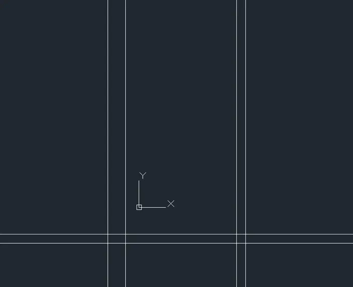
- Enter “offset “ command in the command box.
- Enter the offset distance as 1900mm in the command box.
- Select the “ vertical XLINE” and click by keeping the cursor on right side.
- Click “ESC”.
- Enter “OFFSET” command in the command box.
- Enter the offset distance as 150mm in the command box.
- Select the “Vertical XLINE” and click by keeping the cursor on right side.
- Click “ESC”.
STEP 4:
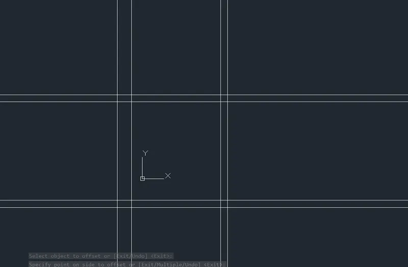
- Enter “offset “ command in the command box.
- Enter the offset distance as 2100mm in the command box.
- Select the “ horizontal XLINE” and click by keeping the cursor on upward direction.
- Click “ESC”.
- Enter “offset “ command in the command box.
- Enter the offset distance as 150mm in the command box.
- Select the “ horizontal XLINE” and click by keeping the cursor on upward direction.
- Click “ESC”.
Step 5:
- Enter “offset “ command in the command box.
- Enter the offset distance as 1700mm in the command box.
- Select the “ horizontal XLINE” and click by keeping the cursor on upward direction.
- Click “ESC”.
- Enter “offset “ command in the command box.
- Enter the offset distance as 300mm in the command box.
- Select the “ horizontal XLINE” and click by keeping the cursor on upward direction.
- Click “ESC”.
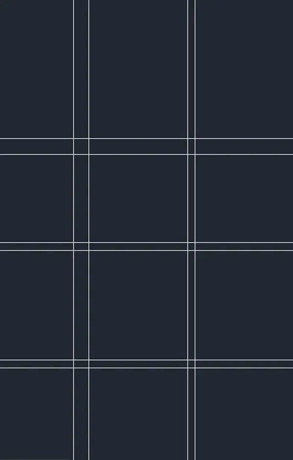
Step 6:
- Enter “TRIM” command in the command box.
- Trim command is activated.
- As per the Sketch given trim off the intersection, corner and unnecessary line.
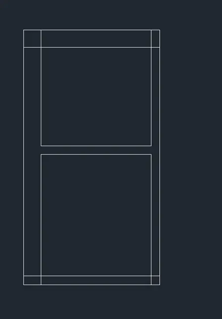
STEP 7
- Enter “REC” command in the command box.
- Specify the starting point as left top corner point.
- Enter “DIMENSION” command in the command box.
- Enter the length as “402mm” and click “ENTER”.
- Enter the breath as “201mm” and click “ENTER”.
- Enter “Offset” command in the command box.
- Enter the Offset distance as “150mm” and select the rectangle.
- Click “ESC”.
- Enter “TRIM” command in the command box.
- Trim of the offsetted rectangle projected downwards
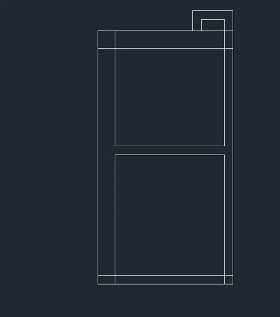
Step 8:
- Enter “LINE” command in the command box.
- Draw a line of random length for reference purpose.
- Enter “offset” command in the command box.
- Specify the offset distance as “100mm” and select the line
- Click “ESC”
- Enter “TRIM” command in command box.
- Trimmed off unnecessary lines.
STEP 9:
- Draw a door length of “832 mm” using “RECANGLE “ command in the command box.
- Select “ARC” tool from home tap.
- Select “Start, End , Direction”. From the drop down list.
- Specify the start and end Direction according to given the sketch.
- Enter “TRIM” command in command box.
- Remove the unwanted lines.
STEP 10:
- Draw a door length of “832 mm” using “RECANGLE “ command in the command box.
- Select “ARC” tool from home tap.
- Select “Start, End , Direction”. From the drop down list.
- Specify the start and end Direction according to given the sketch.
- Enter “TRIM” command in command box.
- Remove the unwanted lines.
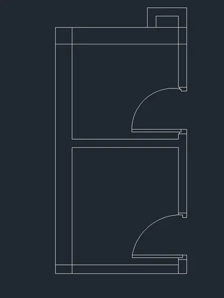
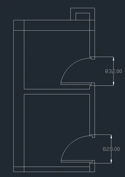
STEP 11:
- Enter “LINE” command in the command box.
- Draw a line at left top corner.
- Enter “OFFSET” command in the command box.
- Enter the Offset distance as “100mm”
- Click “ENTER”.
- Select the line to using offset.
- Enter “offset “ command in the command box.
- Enter the offset distance as “631mm” and click “ENTER”.
- Select the line to offset.
- Draw the small rectangle using rectangle tool on the both sides.
- Draw a line connecting bottom rectangle.
- Using “offset” command , offset line 3times.
- Enter “Line “ command in the command box.
- Draw horizontal line to distance of 728mm.
- Enter “Trim “ command in the command box.
- Trimmed the unwanted lines line.
- Enter “LINE” command in the command box.
- Draw small step using line command along both corner of window using line command.
- At the end point of first step draw rectangle on the other sides also.
- Draw a line from midpoint of first rectangle joining the midpoint point other rectangle using line command.
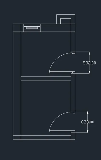
STEP 12:
- Enter “Hatch” command in the command box.
- Fille the bricks in the wall
- Click “Enter”.
- Enter “D” command in the command box.
- Go to the modify tap.
- Enter the “ARROW SIZE AS 100” and “TEXT HEIGHT AS 100”
- Click “SET CURRENT”
- Than click “OK”
- Enter “DIMLINER” command in the command box.
- Show the measurement size of the “ TOILET , UTILITY “WINDOW AND DOORS”.
- Enter “TEXT” command in the command box.
- Click the specify point as inside of the room
- Give a Text height as 100mm and give angle as 0
- Than type the room name and dimension
- Click “ENTER” and enter “ESC”.
RESULTS:
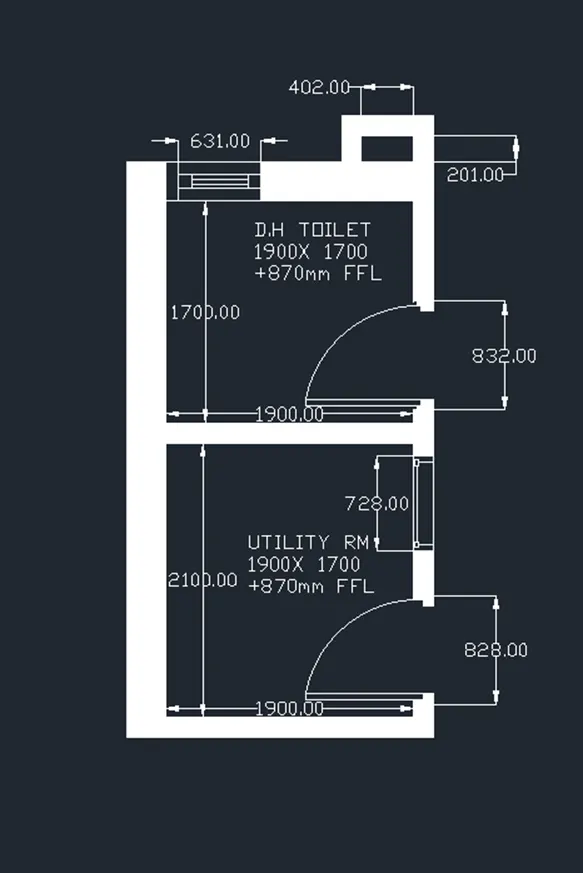
RESULTS FOR :
- Residence Plan:
- outdoor canopy:
- TOILER and Utilities: