Creation of geometries by Coordinate system methods using AutoCad
AIM to make p1 using coordinate system method
PROCEDURE
first l enter then put the coordinate 2,1
then put the value bycounting the boxes
fist put 6 int he x axis
then put 1 in y axis
then put 5 in x axis
then put 4 in y axis
then put 5 in x axis
then put 1 in y axis
then put 6 in x axis
then click close
RESULT we have successfully made the digram using coordinate system
p2
AIM to made p2 figure in autocad using coordinate system
PROCEDURE
first l enter
then specify first point i.e 2,1
then put 3 in x axis
then put 4 in y axis
then put 1 in x axis
then put 4 in y axis
then put 3 in x axis
then put 7 in y axis at an angle
then put 3 in x axis the
click on close
RESULT
we have sucessfully made the figure using coordinate system
example 3
AIM to make the given diagram using autocad software
PROCEDURE
first put the command L enter
then put the value in the command box as follows
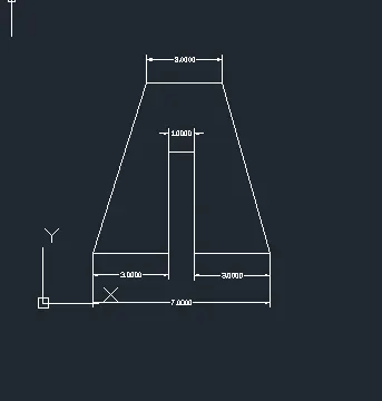
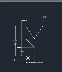
@1,0 / @0,4/ @2,-2/@2,2/@0,-4/@1,0/@0,7/@-1,0/@-2,-3/@-1,0 then click on close
example 4
AIM to draw the given diagram using autocad
PROCEDURE
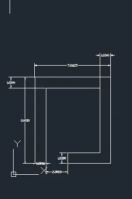
first type L enter
then type the following values in the command box
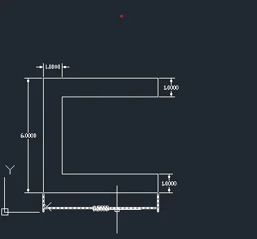
put the value @1,0/@0,7/@5,0/@0,-6/@-3,0/@0,-1/@4,0/@0,8/@-7,0 then press close
and then go to the dimmensions option and click on linear then mark the area accordingly
RESULT we have sucessfully made the drawing using autocad
example5
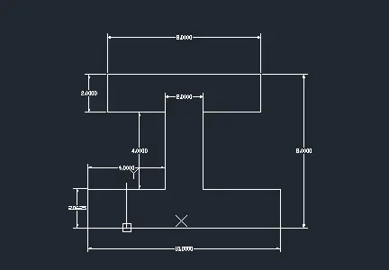
AIM to draw the given diagram in autocad
PROCEDURE
first put L enter
then put the following value in the command tab
first @8,0/@0,2/@-4,0/@0,4/@3,0/@0,2/@-8,0/@0,-2/@3,0/@0,4/@-4,0/@0,-2/ then press close
then go to the dimmension option from the tab and select linear then give dimmensions accordingly
RESULT
we have sucessfully made the drawing using autocad
example6
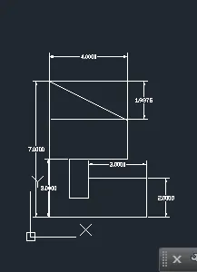
AIM
to draw the given diagram using autocad
PROCEDURE
first type L enter in the command box
then put the following values in the command box
first put 1,1
then @5,0/@0,2/@-3,2/@0,-1/@-1,0/@0,2/@3,0/@0,2/@-4,2 close
then go to the upper tab and select dimmension and then select linear then give the dimmensions accordingly
REESULT
we have sucessfully made the drawing using autocad
example 7
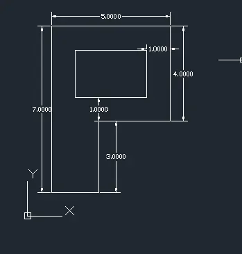
AIM to make the given drawing using autocad
PROCEDURE
first put L enter in the command box
then put the values as follows
@2,0/ @0,3/ @3,0/ @4,0/ @-5,0 then close
after that to make the smaller box
l enter then select a point and give space of 1
then put @0,2 / @0,2 /@-3,0/ @0,-2/ then close again
RESULT
we have sucessfully made the given drawing in the autocad
example 8
AIM
to draw the given diagram using autocad
PROCEDURE
first type L enter then put the following points in the command box
@10<0/ @0,1 /@-2,0 /@0,4/ @2,0 /@0,1 /@5,120
then @0,1 / @2,0/ @0,5/@-2,0 then close
here < is denoted as angel
RESULT
we have sucessfully made the drawing using autocad
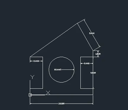
example9
AIM
to make the given diagram using auto cad
NOTE ( i couldnt see the angles and numbers properly because the image is not clear so i have taked the size according to my understanding
PROSEDURE
first type L enter in the command box
then put the folloing values in the command box to make the figure
first specify the starting point (1,1)
then put the value @0,4/@1,0/ @0,1/ @5<65/ @7,0/@0,-4 /@1,0/ @5<45/@0,5 then press close
RESULT
we have sucessfully made the given diagram using autocad
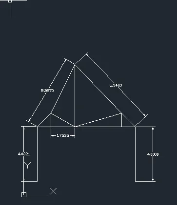
example 10
AIM
to make the given figure using autocad
PROSEDURE
first type L enter
then put the following values in the command box to make this figure
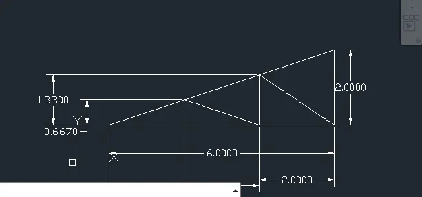
fist put the value @2,0/@0,0.667/ @2,-0.667/ @1.33<90/ @2,-1.33/ @0,2/ @4,0
then go to the dimmension and choose linear and give marking to the lines accordingly
RESULT we have sucesfully made the figure using autocad