Creating a Residence Layout, Seating plan, Toilet and Utility room plan using AutoCad
1. Residence Plan:
Sketch the layout of a residence as shown in the Figure 1. Consider all dimensions as reference to sketch the unit plan. Also the text in the layout are only for reference. Assume the missing dimensions. Also, refer the schedule for size of the doors.
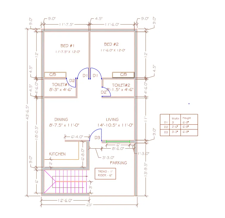
AIM: To draw the given residential plan with the details given.
INTRODUCTION:
Residential layout is ideal for students and practitioners of urban design, planning, engineering, architecture and landscape seeking a comprehensive guide to the thoery and practice of designing and layout out residential areas.
COMMANDS USED:
- limmax command
- limits command
- zoom command
- Xline command
- line command
- Dimlinear command
- Dimstyle command
- units command
- text command
- LW command
- Extended command
- trim command
STEP WISE PROCEDURE:
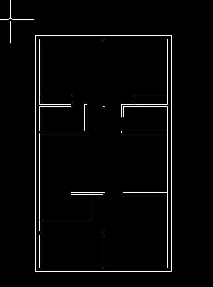
- enter the xline command and draw the line in both x axis and y axis
- make offset of 9" and make a wall.
- partition walls are made of 4.5" thickness.
- next enter the offset command in the command box, then press enter. And select the lines which we have drawn previously and offset the lines to9.0".
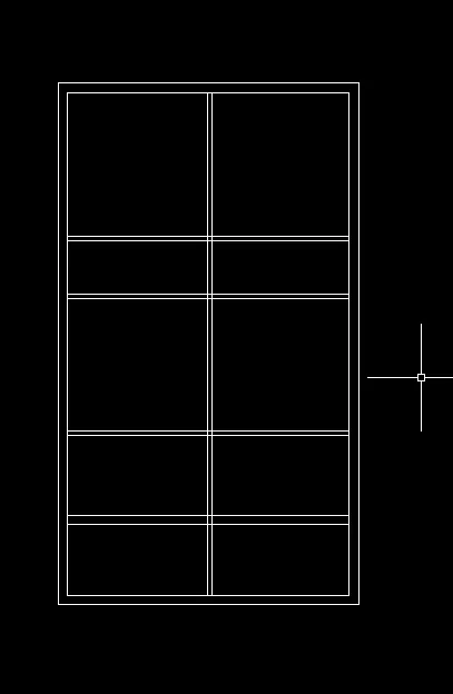
- after providing walls, remove the extra lines using the trim command.
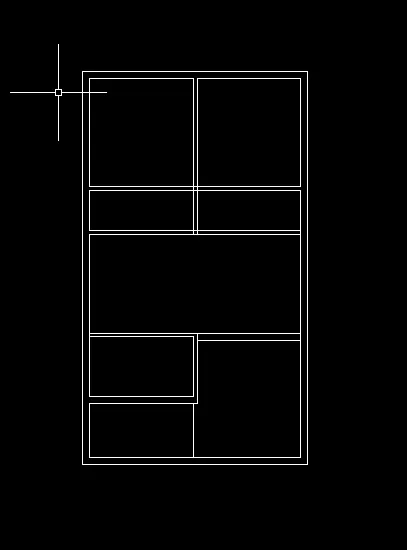
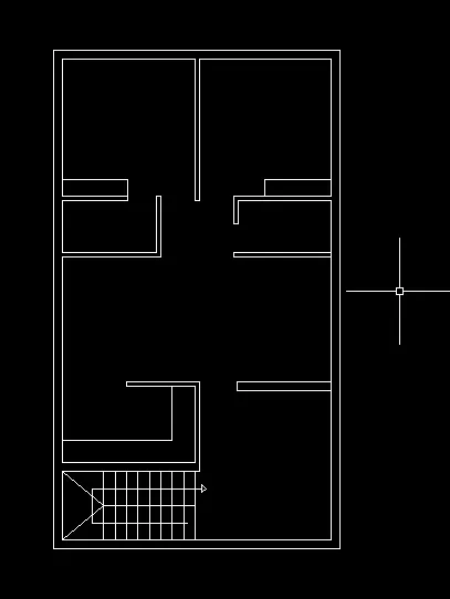
- in the same way offset command is used to parition the rooms, toilets, living and dinning hall as per the dimensions.
- staircase provided is a dog legged stair.
- draw the stairs left side of parking with 1 tread and 6 risee, that is show in the figure clearly.
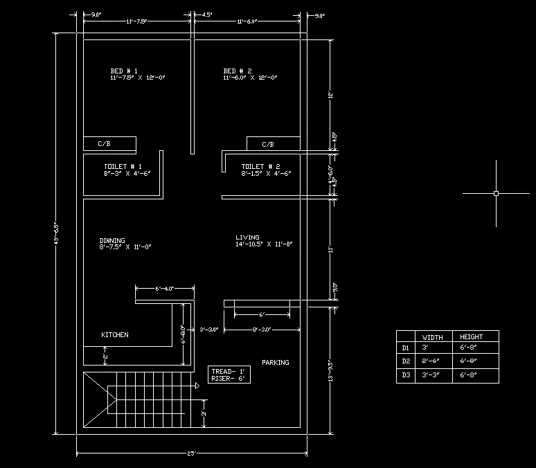
- next we have to draw the door with the given dimensions for d1,d2,d3.
- provide the dimensions.
- differntiate the doors and staircase using different colours.
- and also give the names for rooms in the residential building.
- to provide the names mtext command used.
- from layer property -create a new layer-create 8 layers i.e., wall,door,window,stairs, kitchen, slab and cupboard.
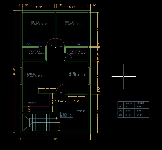
RESULT:
the given residential plan is drawn by using AUTOCAD.
2. Sketch the seating plan for an outdoor canopy. Assume the dimensions for the seating. Also, consider the dimensions in mm.
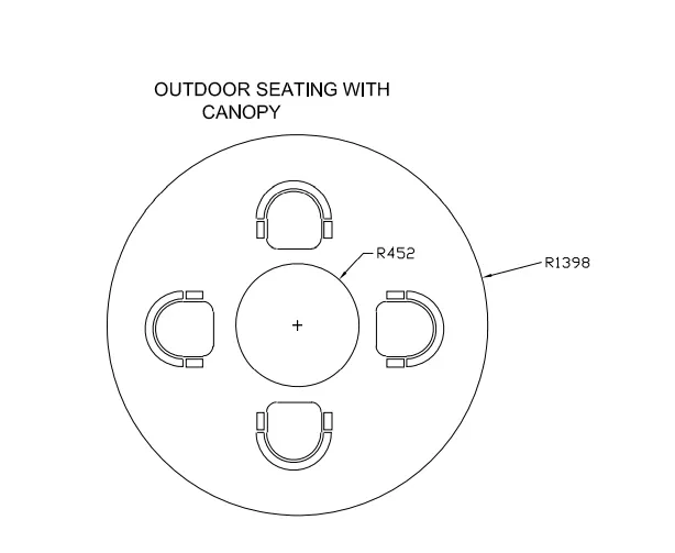
AIM: To draw the given seating plan for an outdoor conopy in detail.
INTRODUCTION:
- A conopy is an overhead roof or else a structure over which a fabric or metal covering is attached, able to provide shade or shelter from weather conditions such as sun,hail,snow and rain.
- canopy can also be a tent, generally without a floor.
- the seating plan of outdoor canopy is places in many, likes receptions, restaurtants etc.
COMMAND USED:
- limmax command
- limits command
- zoom command
- Dimstyle command
- units command
- text command
- LW command
- circle command
- arc command
- array command
STEPWISE PROCEDURE:
command: UN
units
command: C
CIRCLE
specify center point for circle or [3p/2p/ttr(tan tan radius)]:
specify radius of circle or diameter:1398
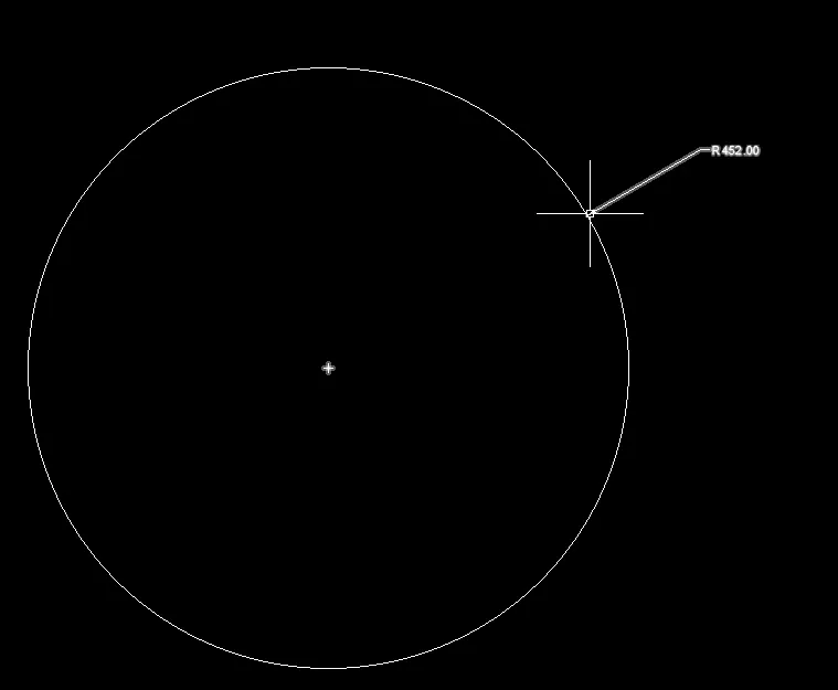
command: C
CIRCLE
specify center point for circle or [3p/2p/ttr(tan tan radius)]:
specify radius of circle or diameter<1398>: 452

- next here we have to drawthe rectangle inside the first circle,then we have to enter the fillet command and select the rectangle corner to fill it.
- next we select the arc command to create arc left side of the rectangle.
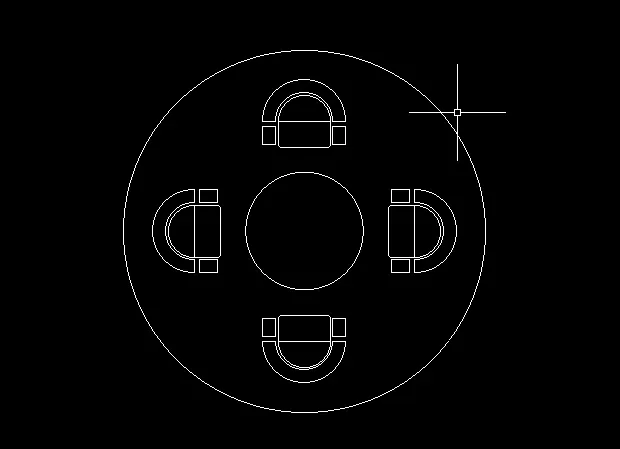
- copy the created chair and use array command.
- by using polar array and providing the number of items as 4 the chairs are createdas shown below.
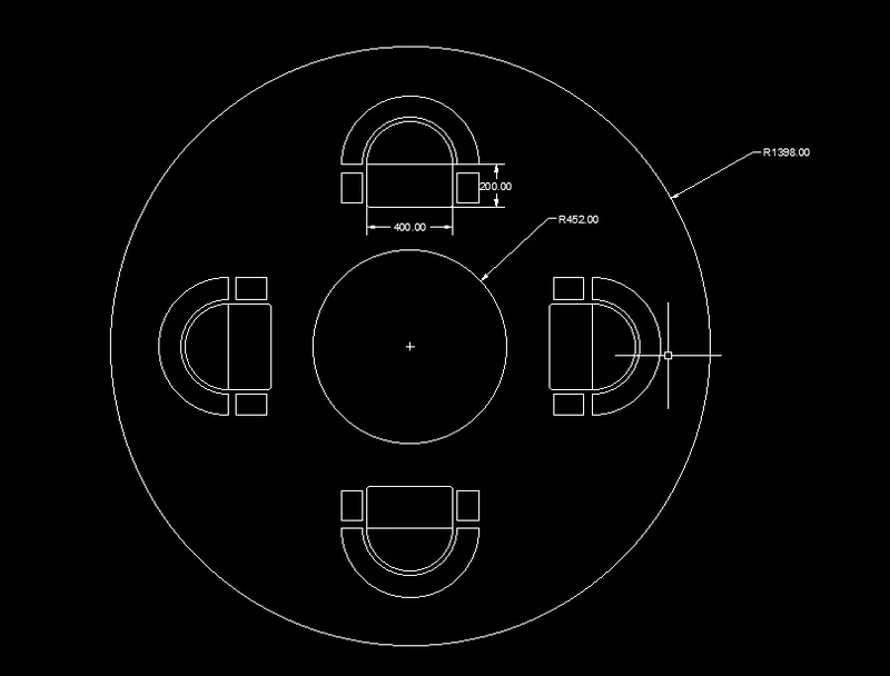
RESULT:
An outdoor conopy is created as per the details given using autocad.
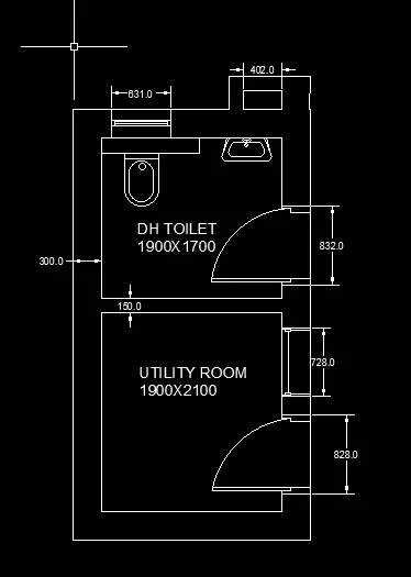
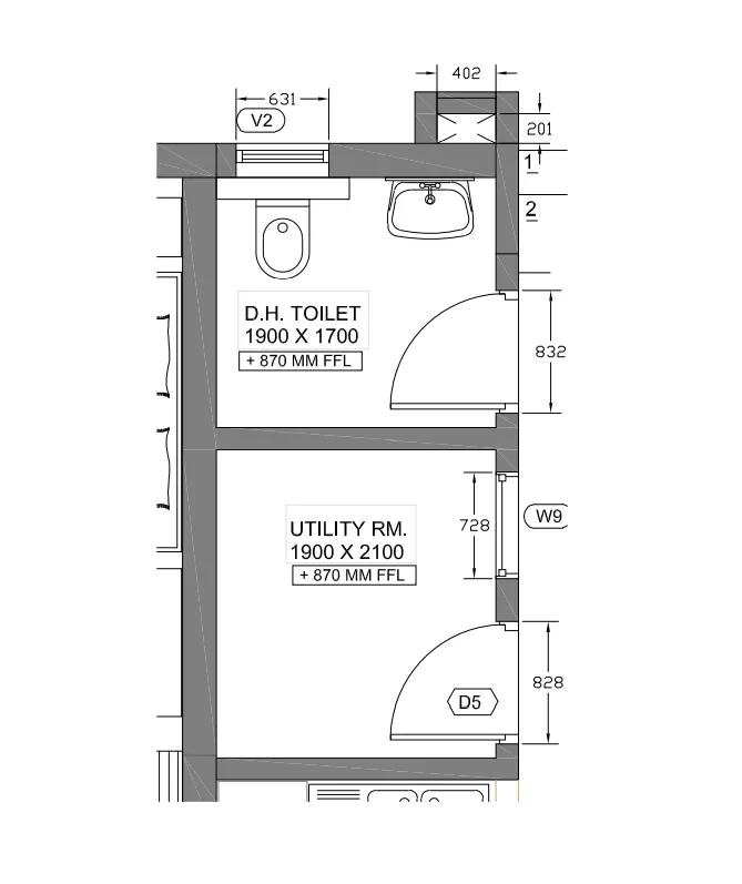
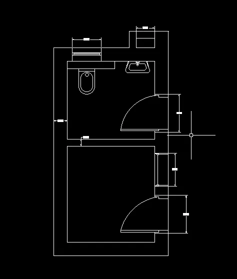
3. Sketch the part plan for the toilers and utilities room. Consider the outer wall thickness as 300mm and inner wall thickness as 150mm. Also, assume the missing dimension, Texts, dimensions, and hatches are only for references. Also, symbols for toilets and w/c are also for references.
AIM:
to draw the part plan for the toilets and utilites in details.
INRODUCTION:
- A toilet room usually consists of obviously a toilet,lavatory and all of the accessones, such as grab bars and dispensers.
- there are many layouts of this type but we will explore pne very simple design and the code requirements for each.
- the utility room has several uses but typically function as an area to do laundary.
- the room contains laundary equipment such as a washing machine , tumble dryer ironing board and clothes iron.
- the room is also used for closet organization and storage.
- the room would normally contain a second coat closet which is used to store seasonal clothing such as winter costs or clothing which are no longer used daily.
COOMANDS USED:
Command:UN
UNITS
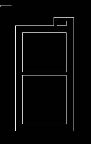
- the lines aare drawn using xline command in both x and y direction.
Command:xline
- the wall thickness is provided as 300mm for the outer walls.
Command:offset
offset distance:300
- the wall thickness for the inside walls are provided as 150mm
Command:offset
offset distance:150
- the wall are provided as per the dimensions given.
- the extra unwanted lines are deleted using trim command.
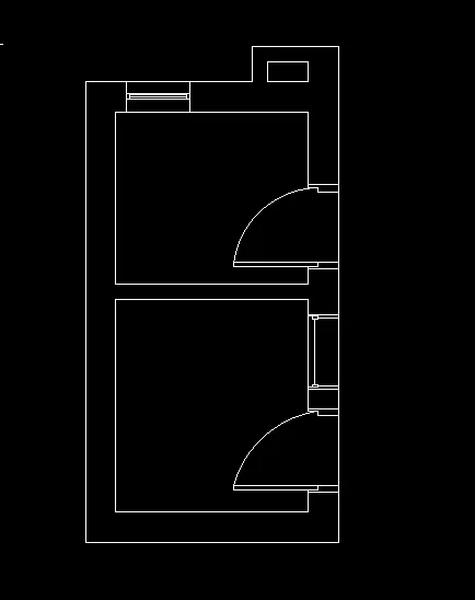
- the door are provided using line and arc command.
- doors are created as per the dimensions.
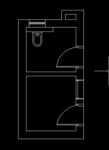
- the toilet basin is created.
- commands used to create the basin are line, arc, ellipse and cricle.
- trim and extened command wherever required.
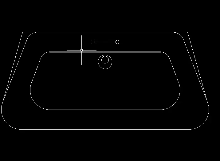
- the wash basin is created.
- commands used are line,arc, fillet.
- ventilation for the bathroomis created.
- commands used were line, trim.
- text is added to the drawing using mt command.
- dimensions of the washroom is provided.
RESULT:
the given plan of the toilet and utilites are created successfully using autocad.