Creation of geometries by Coordinate system methods using AutoCad
Week 1
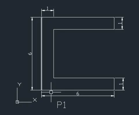
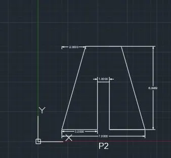
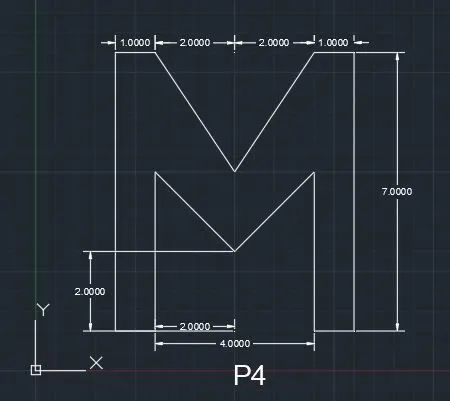
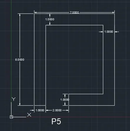
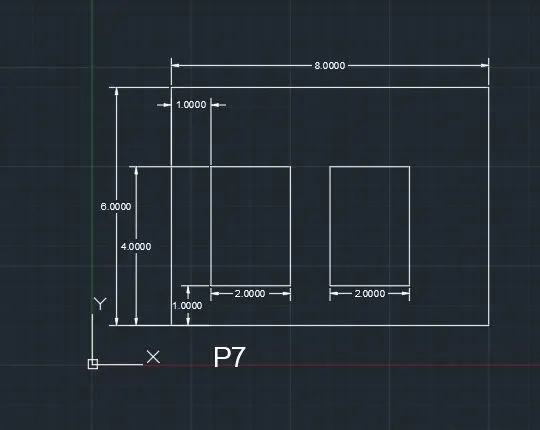
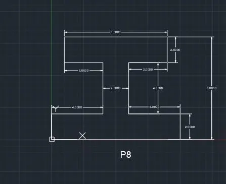
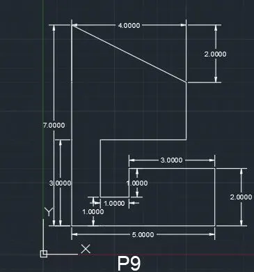
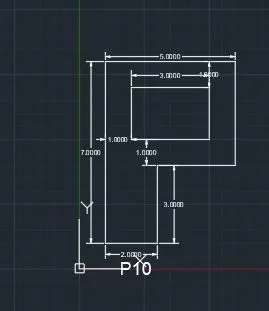
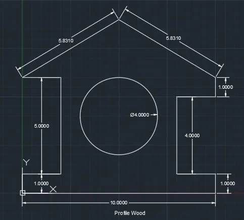
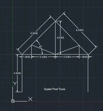
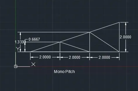
Aim: To create the geometries from P1 to P10 as well as the civil structures namely, Profile wood, Queen post truss and Mono Pitch using all the coordinates system methods.
Introduction: The geometries are constructed in Autocad 2018, using the line tools and the circle tools wherever they are deemed necessary to be used. Here, all types of coordinate systems are incorporated like cartesian, as well as polar coordinate system.
Procedure: The steps adopted for construction of given geometries are as follows.
- Once you start the Autocad application, a start up dialogue box appears which provides options for the unit system which has to be adopted in the drafting i.e. imperial (feet and inches) and metric, additionally the dialogue box also specifies the units of measurement like decimal, engineering, architectural, fractional, scientific etc. and the precision in them to be followed can be varied as desired.
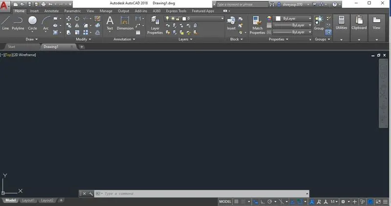
- As shown in the figure, the workspace of autocad, the line command for drafting the geometries can either be selected by clicking it under the home tab or else it can also be written in the command box.
- Once, the user enters inside the Line command, user has to enter the coordinates of the starting point of the line segment which are by default under absolute coordinate system. Once entered, there are various options which can be followed to complete the line segment, which are described as follows:
- One way can be by again adding the cartesian coordinates of the finishing point of the segment in the command box.
- Another way can be of incorporating the polar coordinate system and directly specifying the length of the segment and specifying the angle of inclination with the horizontal in the respective positive as well as negative x and y directions.
- Finally, there is one more way, where if we turn the ortho feature in the software on, we can directly enter the length of the segment. The only caveat is the angles are fixed in the multiples of 90.
- If the geometry consists of circles, then similar to line command, circle can either be selected from the home tab or from the command box. There are various methods through which, the circles can be constructed, which are given as follows:
- By specifying the coordinates of the center and its radius,
- By specifying the coordinates of the center and its diameter,
- By specifying the 2 end points of the diameter. On which the circle can be inscribed
- By specifying 3 points such that all 3 of them lie on the circumference of the circle.
- Specifying 3 line segments as Tangents to the circle such that the circle can be inscribed between the segments.
- After the construction of the geometry, it is also essential to provide dimensions to the segment for comprehensive reading of the drawing. The dimensions can be given using the dimension tool inside the annotation tab in the Home section. Inside the Autocad environment, different types of dimensions can be given namely, Linear, aligned, angular, arc length, radial, diametric etc.
Results:
The provided geometries from P1 to P10 and additionally the civil structures namely the queen post truss, mono pitch and profile wood are drafted in Autocad 2018 with the accurate dimensions as provided.