Creating a Floor plan, Footing detail and Isometric view using AutoCad
Aim : To create a Floor Plan, Isometric view and Footing detail using Autocad.
Introduction : The respective Floor Plan, Isometric views as well as footing details are drafted in Autocad 2018. The tools used in the process are the line tool, dimension tool, offset tool, fillet tool, trim tool and champher tool. Here, all types of coordinate systems are incorporated like cartesian, as well as polar coordinate system.
Procedure:
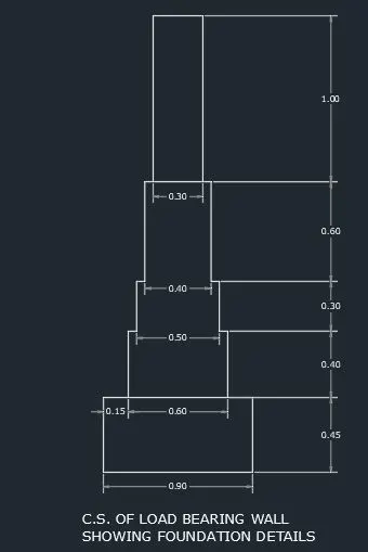
- The procedure for drafting of the C.S of the load bearing wall with the foundation details is as follows:
- After studying the figure, Line tool is used by pressing L + Enter on the command line and here, the ortho mode is switched on throughout the process.
- Apart from the line command, Offset command is also used to speed up the drafting process by pressing O + Enter in the command box, to draft lines parallel to the existing lines at the specified distances.
- Finally, after the construction of figure, dimension command is used by pressing dim + enter from the command box and the respective dimensions are drafted, enabling the drawing to be studied with ease.
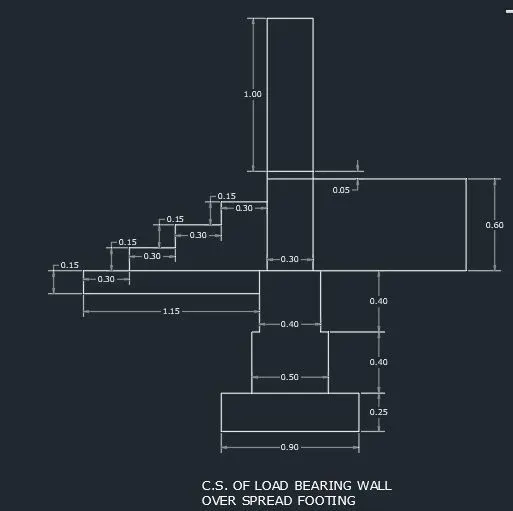
- The procedure for drafting the C.S of the load bearing wall over spread footing is as follows:
- After studying the figure, Line tool is used by pressing L + Enter on the command line and here, the ortho mode is switched on throughout the process.
- Apart from the line command, Offset command is also used to speed up the drafting process by pressing O + Enter in the command box, to draft lines parallel to the existing lines at the specified distances.
- Finally, after the construction of figure, dimension command is used by pressing dim + enter from the command box and the respective dimensions are drafted, enabling the drawing to be studied with ease.
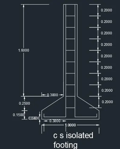
- The procedure for drafting the C.S of the Isolated footing is as follows:
- After studying the figure, Line tool is used by pressing L + Enter on the command line and here, the ortho mode is switched on throughout the process.
- Apart from the line command, Offset command is also used to speed up the drafting process by pressing O + Enter in the command box, to draft lines parallel to the existing lines at the specified distances.
- Additionally, Fillet command by F + Enter in the command box is used to curb the extended line segments than desired more efficiently.
- Finally, after the construction of figure, dimension command is used by pressing dim + enter from the command box and the respective dimensions are drafted, enabling the drawing to be studied with ease.
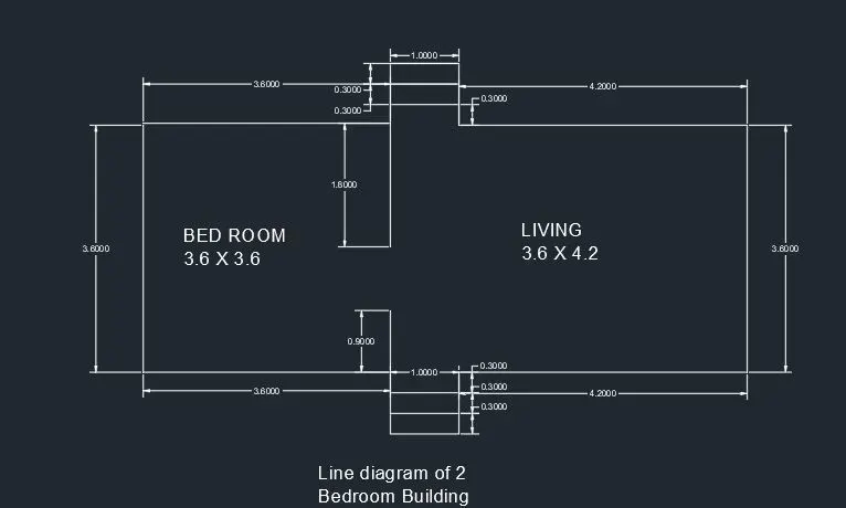
- The procedure for drafting the Line diagram of the two Bedroom Floor Plan is as follows:
- After studying the figure, Line tool is used by pressing L + Enter on the command box and here, the ortho mode is switched on throughout the process. Using the Line command, the rooms desired i.e. the bedroom and the Living room are constructed as well as their separators.
- Apart from the line command, Offset command is also used to speed up the drafting process by pressing O + Enter in the command box, to draft lines parallel to the existing lines at the specified distances. This is especially used while drafting the staircase parts i.e. while drafting the steps.
- Additionally, Fillet command by F + Enter in the command box is used to curb the extended line segments than desired more efficiently.
- Subsequently, after the construction of figure, dimension command is used by pressing dim + enter from the command box and the respective dimensions are drafted, enabling the drawing to be studied with ease.
- Finally, text command is used from the annotation panel from the Home ribbon, to enable the user mark the difference between both the constructed rooms.
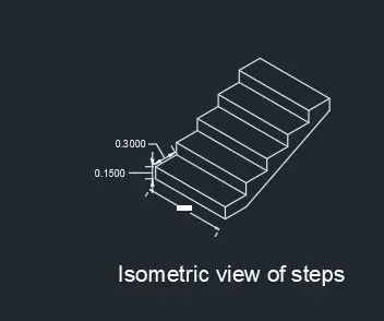
- The procedure for drafting the Isometric view of staircase is as follows:
- For drafting on isometric view, the prerequisite steps are to switch on the display of the drawing grid, and also to turn on the snap mode. Here ortho mode is switched on. Additionally, the isometric planes in left, right and top can be switched as and when desired. All the above mentioned functions or commands are available on the toolbar usually positioned at the bottom right corner of the workspace in Autocad.
- After studying the figure, Line tool is used by pressing L + Enter on the command line to construct the steps of the desired proportion.
- Apart from the line command, Offset command is also used to speed up the drafting process by pressing O + Enter in the command box, to draft lines parallel to the existing lines at the specified distances.
- Subsequently, after the construction of figure, dimension command is used by pressing dim + enter from the command box and the respective dimensions are drafted, enabling the drawing to be studied with ease.
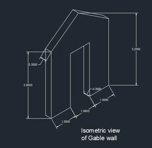
- The procedure for drafting the Isometric view of the Gable wall is as follows:
- For drafting on isometric view, the prerequisite steps are to switch on the display of the drawing grid, and also to turn on the snap mode. Here ortho mode is switched on. Additionally, the isometric planes in left, right and top can be switched as and when desired. All the above mentioned functions or commands are available on the toolbar usually positioned at the bottom right corner of the workspace in Autocad.
- After studying the figure, Line tool is used by pressing L + Enter on the command line to construct the wall of desired proportion including the openings and giving the desired thickness.
- Apart from the line command, Offset command is also used to speed up the drafting process by pressing O + Enter in the command box, to draft lines parallel to the existing lines at the specified distances. This command comes especially handy while defining the desired thickness of the wall.
- Subsequently, after the construction of figure, dimension command is used by pressing dim + enter from the command box and the respective dimensions are drafted, enabling the drawing to be studied with ease.
Results:
The provided Floor Plan, isometric views and the footing details are drafted in Autocad 2018 with the accurate dimensions as provided.