Creation of Column Schedule and Drawing Template using AutoCad
CREATION OF COLUMN SCHEDULE AND DRAWING TEMPLATE USING AUTOCAD
Introduction:
For creating a column schedule and to draw a template, the main tools used in AutoCAD are line tool, text, annotation etc.
- Line:
- Command used is L or line. It can also be evoked from ribbon, tool bar, menu bar.
- It is most common nd basic tool in AutoCAD.
- First we have to specify the starting point and then follow the command to complete the geometry uing line tool.
- Annotation objects:
- Annotation objects include dimensions, notes and other types of explanatory symbols or objects commonly used to add information to your drawing.
- It provides information about a feature, such as length of a wall.
- Annotation objects are scaled differently than the views of the drawing, and depend on the scale of how they should appear when plotted.
- Common annotations that can be created in a drawing are notes and labels (single line and multiline text), tabular data(table), dimensions and geometric tolerences, hatches, gradients and fills, notes and symbols with leaders, title block and attributes.
- Annotation scales:
- Annotation scale is used to determine text height or the overall scale of an annotation object.
- The approach used to calculate an annotation scale depends on whether the object is placed in model space or layout.
- The text height or scale of an annotation objectin model space can be set to a fixed text height or be controlled by assigning the object an annotation scale.
- Annoattaion objects assigned fixed text height or object scale remain proportionate in size to the current plot or viewport scale.
- If annotative property of an annotation object is enabled, the text height or scale of the annotation object adjusts based on the current drawing annotation with the result that it will remain at the same size automatically.
- Now, the annoattaion objects created in paper space on a layout should be craeted at full size because layouts are commonly plotted at a 1:1 scale.
- Text : Two types - Multiline text and Single line text.
- Multiline text: For longer notes and laels with internal formatting, use multiline text.
- Click home tab ---> Annotation panel ---> Multiline text. Command: MTEXT.
- Specify the opposite corners of a bounding box to define the width of the multiline text object. If the ribbon is active, the Text editor contextual tab displays. If the ribbon is not active, the Text formatting toolbar displays.
- Specify the initial formatting:
- To indent the first line of each paragraph, drag the first line indent slider on the ruler.To indent the other lines of each paragraph, drag the hanging indent slider.
- To set tabs, click the ruler where you want a tab stop.
- To change the current text styles, select the desired text style from the dropdown list.
- Enter the text (while typing text may be dispalyed horizontally).
- To change the individual characters, words or paragraphs, highlight the text and specify the formatting changes.
- Single line text: For short, simple notes and labels, use single line texts.
- Click home tab ---> Annotation panel ---> single line text. Command: DTEXT.
- Specify the insertion point. If you press enter, the program inserts the new text immediately below the last text object you created, if any.
- Enter a height or click to specify the height of the text . If a specific height is set in the currrent text style, this prompt is skipped.
- Enter an angle value or click to specify the rotation angle.
- Enter the text, while typing the text may be displayed horizontally.
- To create another single line text, do one of the following:
- Press ENTER to start another line of text immediately below.
- Click a location for the next text object.
- Multiline text: For longer notes and laels with internal formatting, use multiline text.
1.
Aim:
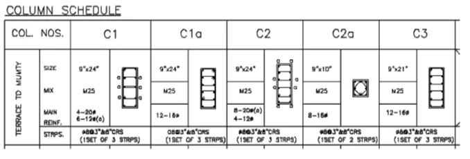
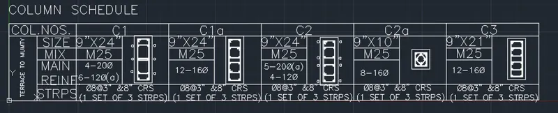
To create the column schedule using line tool and single line text in AutoCAD as shown in the figure.
Procedure:
- Initially set the units as Architectural (feet and inches).
- Here, there are four columns as shown i.e C1, C1a, C2, C2a, C3.
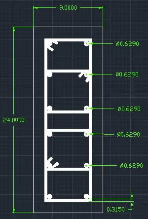
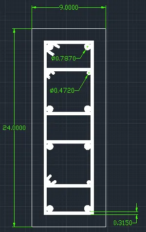
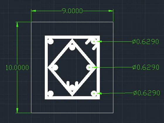
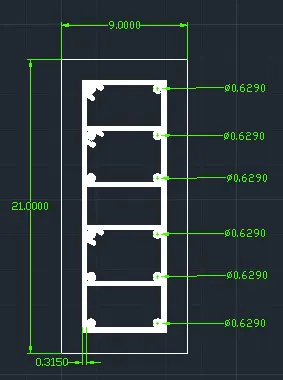
- The column C1 contains 4 no.s of 20mm dia bars and 6 no.s of 12mm dia bars (a); C1a contains 12 no.s of 16mm dia bars; C2 contains 8 no.s of 20mm dia bars; C2a contains 8 no.s of 16mm dia bars; C3 contains 12 no.s of 16mm dia bars.
- Stirrups are having bar dia of 8mm placed at a c/c spacing of 3" near the ends and 8" at the middle.
- According to IS456:2000, for a column the nominal cover should not be less than 40mm in any case. Hence provide 40mm nominal cover for column i.e 1.5" (approx).
- Now, we have to convert the units of bar diameters from mm to inches (length/25.4). The converted values are given in the folllowing table:
| Bar diameter in mm | Bar diameter in inches |
| 20 | 0.787 |
| 16 | 0.629 |
| 12 | 0.472 |
| 8 | 0.315 |
- Initially create the column C1:
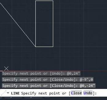
- Using the line option, create the outline of the column(9"x24") (using absolute coordinate system).
- Now offset these lines inwards at an offset distance of 1.5" which is the nominal cover to column reinforcement and then trim off the extending part.
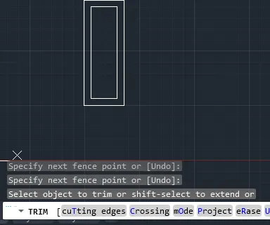
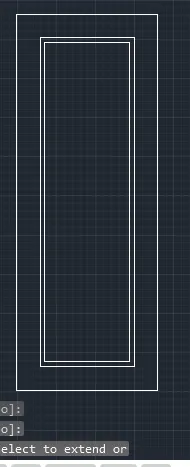
- Again offset these lines inwards at an offset distance of 0.315" which is the dia of the stirrups.
- After this, offset the top horizontal line downwaards to obtain the stirrups at 3" and 8" c/c.
- Now choose the circle command and draw circle of radius 0.787" and then copy this circle to the four corners. These bars are main reinforcement bars of dia 20mm.
- Again, choose the circle command and draw circle of radius 0.472" and then copy this circle to the six corners within. These bars are also main reinforcement bars having dia 12mm.
- Now hatch the entire portion of reinforcement. Hence, the column C1 is complete.
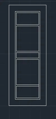
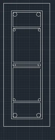
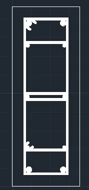
- Column C1
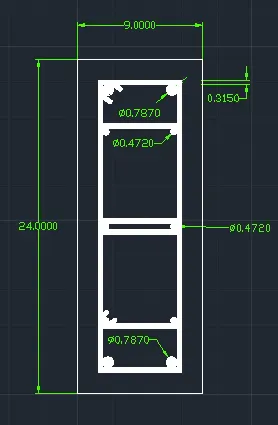
- Similarly complete the rest of the columns:
- Column C1a
- Column C2
4. C2a
5. C3
- Hence, all the columns have been created.
- Now, create the table as given in figure using line tool in AutoCAD and fill in the contents using single line text and the font used is roman.shx and text height is 8".
2.
Aim:
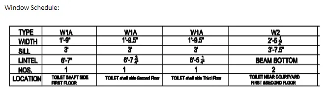
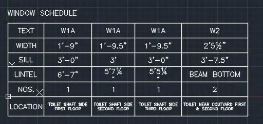
To create the window schedule as given below:
Procedure:
- Initially set the units as Architectural-Imperial (feet and inches).
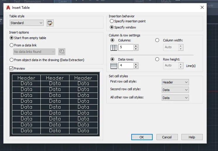
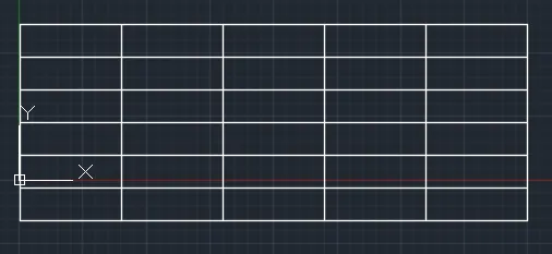
- Now, choose the table command and create a table having 5 columns and 6 rows.
- The table so obtained is given below:
- After that insert the contents within the table using mutiline text (MTEXT) . Font: romans.shx and text height: 8"
3.
Aim:
- To create the drawing template as shown in below figure:

Procedure:
- Initially set the units of the drawing as Architectural- Imperial (feet and inches).
- Create the table using the line command in AutoCAD by inserting 6 columns and 5 rows as given below:

- Now, fill in the contentswithin the table using the MTEXT command(multiline text):

4.
Aim:
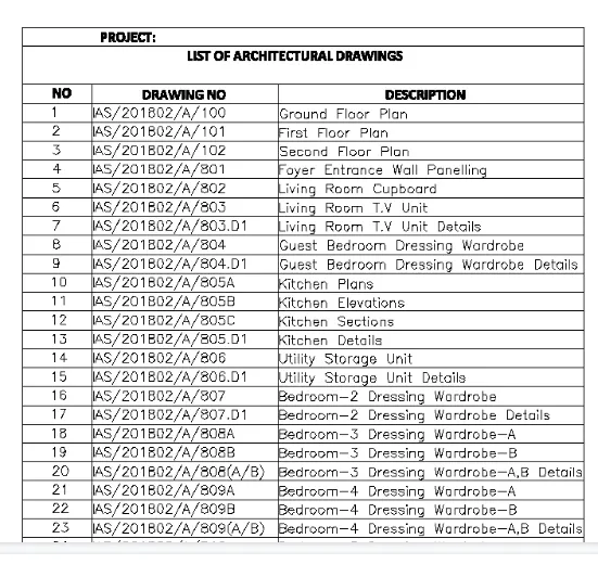
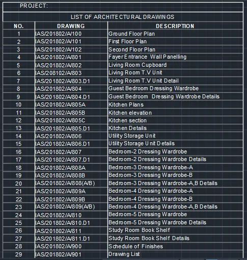
- To create the list of drawing schedule as shown in the figure:
Procedure:
- Initially set the units as Architectural- Imperial(feet and inches).
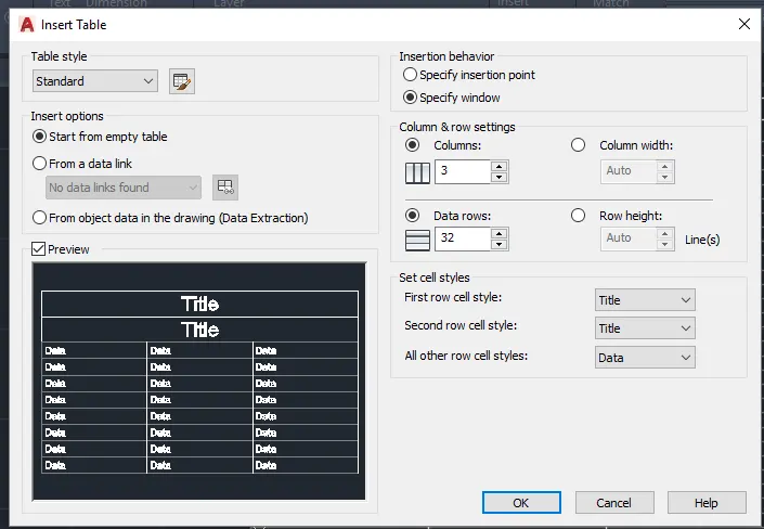
- Now, create the table using the table command in AutoCAD with 32 rows and 3 columns.
- The table created is as follows:
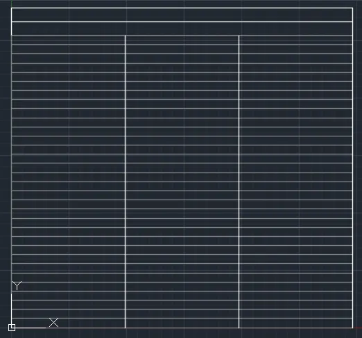
- Now insert the contents in the table above.
5.
Aim:
To create the beam detail as given in the figure and then provide the text wherever necessary.
Procedure:
- Initially set the units as Architectural- Imperial (feet and inches).
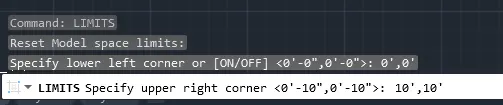
- Now, set the limits of the drawing:
- Specify the lower left corner: (0'0",0'0")
- Specify the upper right corner: (10',10')
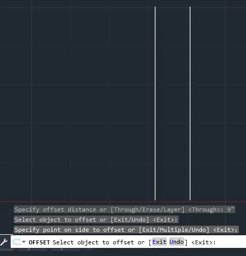
- Now, choose line command and draw a line 50" long, and then off set this line at an offset distance of 9", obtain two parallel lines.
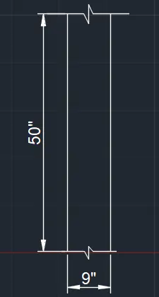
- Now, using break line command put break line at top and bottom.
- Now, using the line command draw horizontal line as given in the figure at 20" from bottom draw one line and then offset these lines upwards at an offset distance of 3" and 9" respectively .
- Then the top two horizontal lines are extended towards right as shown below:
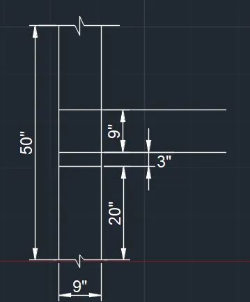
- Now, dimension it according to the given figure:
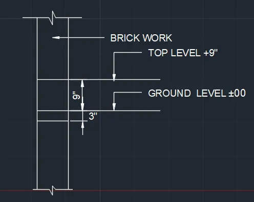
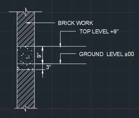
- Now, hatch the concrete and brickwork portion.
Result:
1. Column schedule created is given below:
2. Window schedule created is given below:
3. Drawing templated created is given below:
4. The list of drawing schedule created is as given below:
5. Beam detail created is as given below: