Creation of Column Schedule and Drawing Template using AutoCad
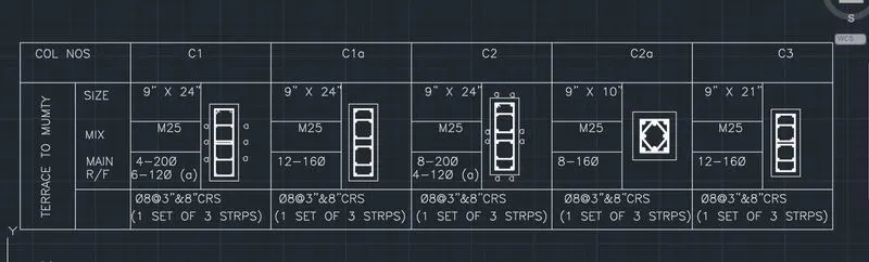
AIM-1: To create a column schedule as shown in figure.
Introduction:
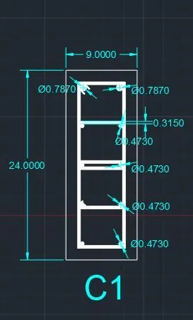
- Column C1 is provided with 4 bars of 20 mm dia, and 6 bars of 12 mm dia. The 12 mm dia bars are marked with ‘a’.
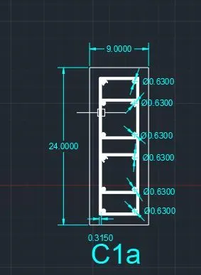
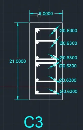
- Column C1a and Column C3 are provided with 12 bars of 16 mm dia bars.
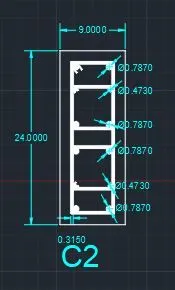
- Column C2 is provided with 8 bars of 20 mm dia and 4 bars of 12 mm dia. The 20 mm dia bars are marked with 'a’.
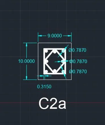
- Column C2a is provided with 8 bars of 16 mm dia.
- All columns are provided with 8 mm dia. stirrups with 3" spacing cc near the ends and 8” cc in mid-length.
- The clear cover for all the columns is assumed to be 1.5" (approx 40 mm). As per IS 256, the minimum cover to the column should not be less than 40 mm.
Procedure:
- Open a new AutoCAD file in Imperial units.
- Convert the diameter of the bars into inches. By dividing by factor of 25.4.
- Make the column C1 as shown.
- Make the column C1a as shown.
- Make the column C2 as shown.
- Make the column C2a as shown.
- Make the column C3 as shown.
- Make the table as shown with new text style and font as romans.shx and height 8”.
- Scale the columns made in the previous steps by a factor of 3.5 to make them fit inside the table.
Result:
AIM-2: To create a window schedule as shown in the figure.
Introduction:
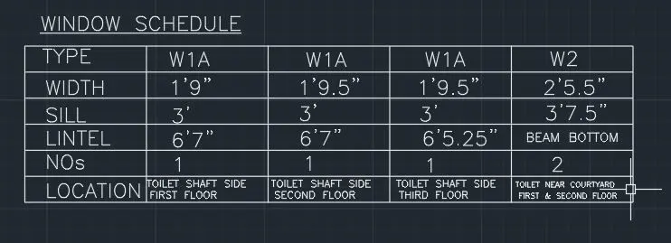
The given table contains the width, lintel and sill heights of the windows and their respective locations for different type of beams.
Procedure:
- Construct the following table as shown in the figure.
- With multi-line text command, fill in the given data while keeping the justification center MC.
Result:
AIM-3: To create a drawing template as shown in figure.
Procedure:
- Construct the following table as shown in the figure.
- With multi-line text command, fill in the given data while keeping text height at 2.5” and font as arial.
Result:

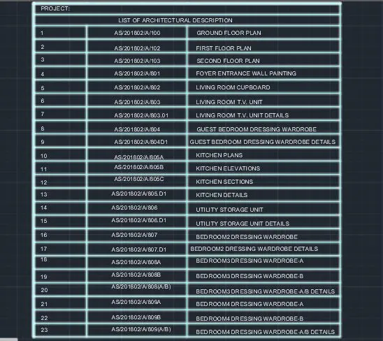
AIM-4: To create the list of drawing schedule as shown in the figure.
Procedure:
- Open the table command and select the preferences accordingly by adjusting the title rows and selecting the height of the cells and specifying the number of rows and columns as desired.
- Adjust the sizes of the rows and columns.
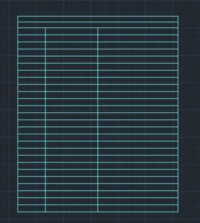
- Fill in the data as given in the figure using text command.
Result:
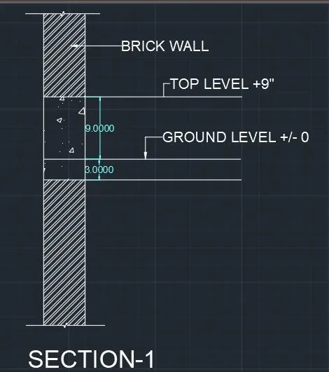
AIM-5: To create the beam detail as shown in the figure and to provide text for top as well as ground level where given.
PROCEDURE
- Make two parallel lines 45" long at a distance of 6" from each other.
- Using the break-line command, make a break-line at the top and bottom.
- Make the horizontal lines as shown in figure.
- Give the required labelling using leader and multi-text commands.
- Modify the dimensions to be matched by the same given in the question.
- Give the Hatching of Brickwork and Concrete as shown.