Creation of Column Schedule and Drawing Template using AutoCad
Q.1
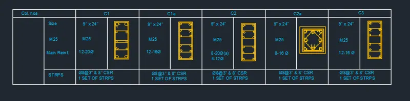
Ans. The given question is below
AIM To create a column schedule, and to draw the column showing reinforcement of the columns in detail
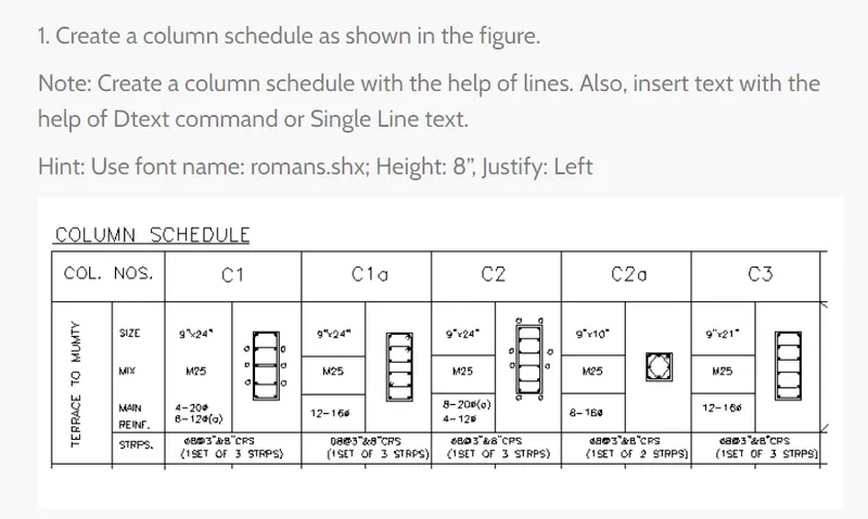
Procedure : The command used to draw given column schedule are as:
- Limits command
- Single Text command
- Line command
- Dimlinear command
- Trim command
- Mtext command
- Circle command
- object snap command
- Divide command
- Mirror command
Steps
- Open the autocad and set the limits and units
- First we have to draw the table using the line command
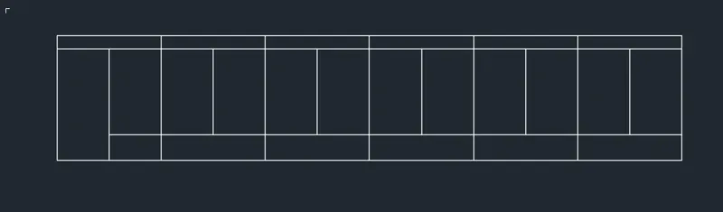
- Nowe we need to enter the details of columns with Single text and Mtext command
- we draw the line with the length of 9" horizontally
- draw the 24" line vertically, then again draw the line with the length of 9"
- join the first line and last line
- after we do offset of 0.6", and do the offset to inside of rectangle
- now draw a circle beside of the previous figure , we take the circle diameter as 20mm
- draw another circle as diameter 12mm
- use the divide command and give the 4 segments inside the rectangle
- now place the circle in the every segment
- put the 3 stirrups in the column where they are required to put in certain position
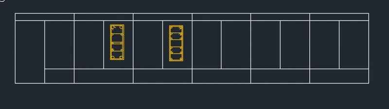
- we need to enter the details of columns with Single text and Mtext command
- we have to the this overall column data in the table which we have draw first, as shown in above table
- Repeat the above procedure
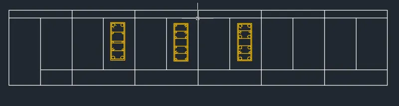
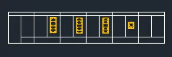
- we need to enter the details of columns with Single text and Mtext command
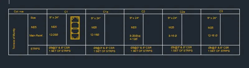
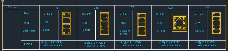
Final Result
Q.2
Answer 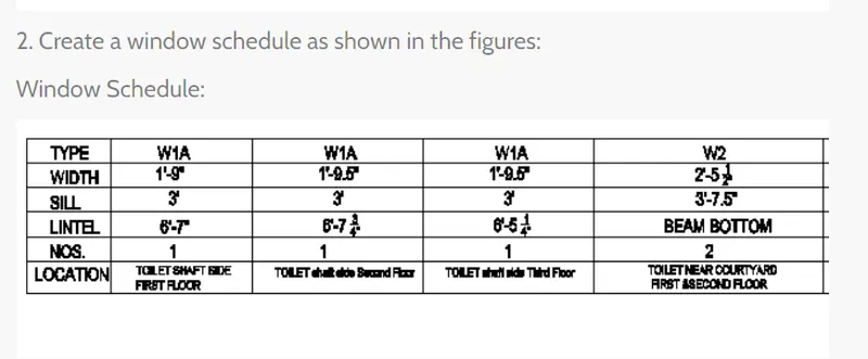
AIM To create a window schedule, and to draw the details of windows for construction purpose
Introduction The window schedule is a schedule which the details of the windows in construction can be collected in the table form, that is why we collect the window details in the form table for the construction purpose
Procedure Command used are as
- Limits command
- Single Text command
- Line command
- Dimlinear command
- Trim command
- Mtext command
- open the autocad and set the limits and units
- we have to draw the table using the line command as shown in below table
- raw the 5 columns and the 6 rows for the window scheduling
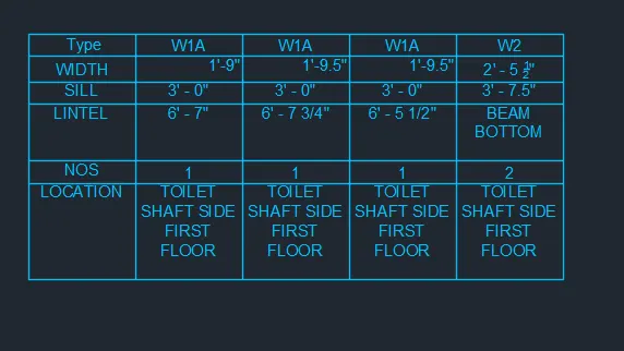
- we enter the details of the various windows in the window schedule
- we draw the window schedule and enter the details of them in the tabular form
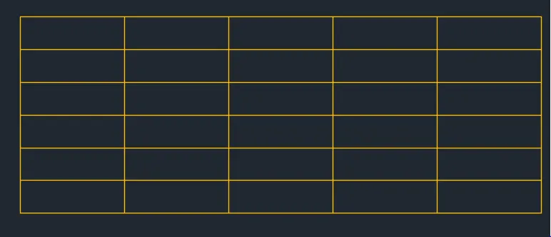
- we drawn the window schedule and written their details in the table as shown in figure
- Final Result
Q.3
Ans.
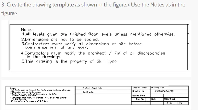
AIM To create the drawing template for entering the details of the project
Introduction drawing template are used to enter the details of the project details
Commands used are
- Limits command
- Limits command
- Single Text command
- Line command
- Units command
STEPS
- open the autocad and set the limits and units
- draw the table using the line command as shown in below table
- table is for the entering the details of the entire project before submitting to the client
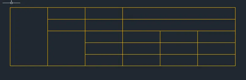
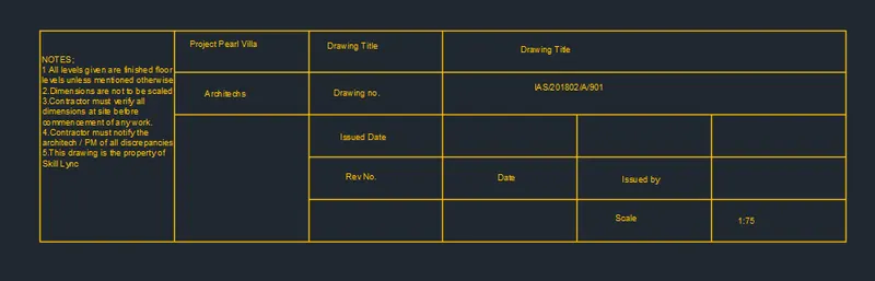
- After drawing the table we have to select the Mtecxt command to enter the notes and project details
- he text height will be kept to 8", and it is the standard text height for entering the details of the project in the table.
- Result
Q. 4
Ans 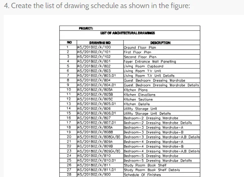
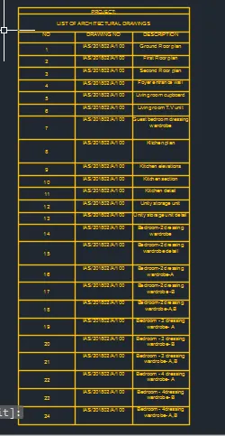
AIM To create the list of drawing schedule and to be listed in detail
Introduction A schedule of drawings is an itemised list of drawings required for a building project, schedule of drawings may include all the drawings required for a project
Procedure Command used are as
- Limits command
- Table command
- Single text command
- Extend command
- Dimlinear command
STEPS
- open the autocad and set the limits and units
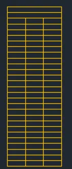
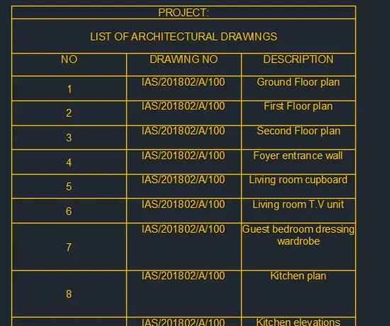
- we have to enter the Table command for creating the list of drawing schedules
- After entering the table command the table setting screen will be displayed as shown in figure
- use the single text command for texting in the table
Final Result
Q 5
Ans 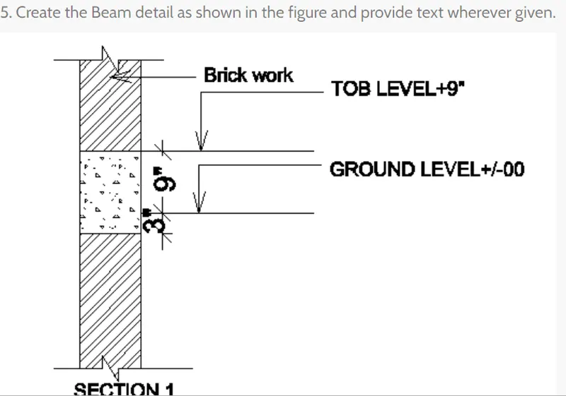
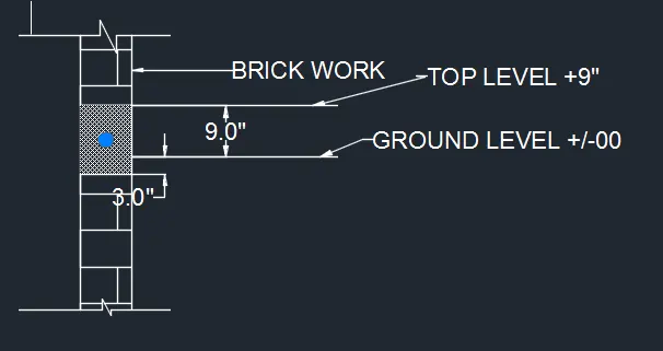
AIM To create the beam detail as shown in the figure and provide text for top level and ground level
Introduction structural element that primarily resists loads applied laterally to the beam's axis,loads applied to the beam result in reaction forces at the beam's support points
Procedure Command used are
- Limits command
- Line command
- Dimlinear command
- Trim command
- Mtext command
- Leader command
STEPS
- open the autocad and set the limits and units
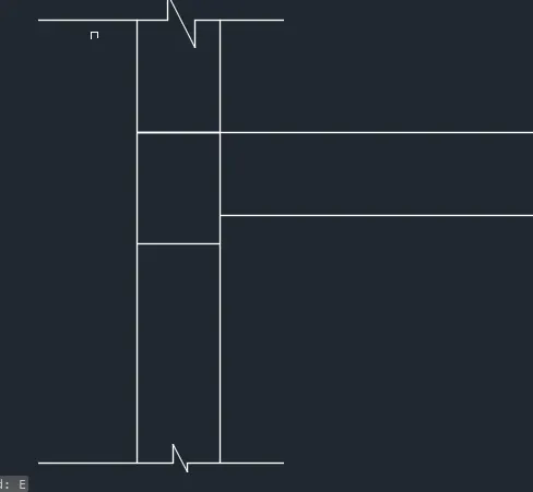
- enter the line command and draw the line of length 4' vertically
- again draw the line of length 9" horizontally forward
- again draw the line of 4' length vertically upwards
- draw the line horizontally backwards of length 9"
- join the first line and the last line, then we will find the rectangle

- from rigtht corner at bottom leave the distance of 1'-5" upwards and draw a line from that distance, it is a ground level
- from previous point we leave the distance of 9" and draw a line horizontally forward from that distance, that line we call the top level
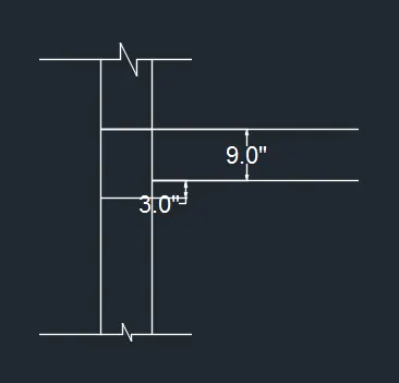
- now we have to put the dimentions for the ground level, its distance is 3"
- we have to put the dimensions from the ground level to the top level, the distance is 9"
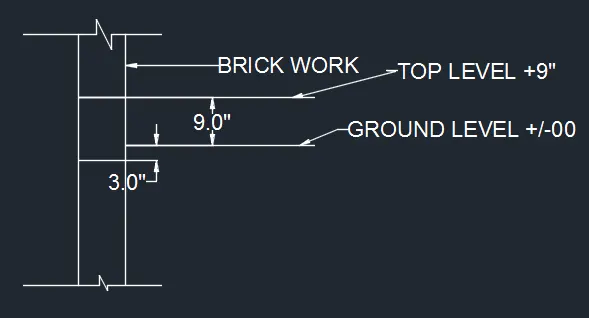
- Now provide the texts for the particular parts, they are brick work, Top level and Ground level
- The beam with the texts mentioned are shown in below figure
- Now we have to use the Hatch command to hatch the different parts in the diagram
- hatched with various hatches with Hatch command as shown in the below figure
- Result