Creating a Floor plan, Footing detail and Isometric view using AutoCad
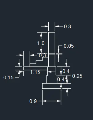
AIM 1:- To draw a cross section of load bearing wall over spread footing
Introduction : To draw a cross section of load bearing wall over spread footing by Autocad
Procedure :
- Line command to make rectangle of 0.9 width and 0.25 length
- Take a distance of 0.2 from left and right and in Y direction for 0.4
- then take 0.05 from from left and right and in Y direction for 0.4
- then take 0.05 from from left and right and in Y direction for 0.3
- now take Line command in -Y direction 0.15 and take distance of 1.15 in-X direction
- Above step is repeted and command used is Line
- Dimension command for dimensioning
Result :
- .
AIM 2:- To draw a cross ssection of isolated footing
Introduction : To draw a cross ssection of isolated footing by Autocad
Procedure : Line command uses to create a line
Trim command is used to trim the extra lines
Extend command used to extend the line
Offset command is used to take offset of 0.04 for bar and spacing 0.2
Result 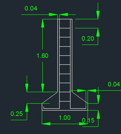
AIM 3:- To create line diagram of two building
Introduction :- To create line diagram of two building by Autocad
Procedure : Line command is used to create a rectangle of 3.6 X3.6 , stair 1 X 0.3 and living room 3.6 X 4.2
Offset command of 0.3 is used to draw a stair
Result :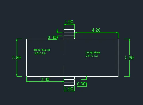
AIM 4:- Draw cross section of bearing wall showing Foundation detail
Introduction:- Draw cross section of bearing wall showing Foundation detail by using Autocad
Procedure:-
- step 1 create a rectangle by typing RFC in command box
- create a rectangle of 0.9 X .45
- step 2 take a line command and market distance of 0.15
- next create a line with unit of 0.4 in y axis on both side
- step 3 take a line command and market distance of point 0.05
- next create a line with unit of 0.3 in y axis on both side
- step 4 take a line command and market distance of .05
- next create a line which unit of 0.6 in Y direction on both side
- step 5 take a line command and market distance of .05
- next create a line with unit of 1.0 in y axis on both side
Result :-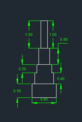
Aim 5:- To draw the isometric view of steps
Introduction :- To draw the isometric view of steps by using AutoCAD
- Procedure:-
- type DS in command box keep the isometric snap on and off the grid and snap off make sure that ortho mode is on
- step 1 from the isometric drafting select the left isoplane take the line command and create a verticle unit of 0.15 from the both in line
- move the cursor to x-axis and joined the line
- step 2 change the plane to top take the cursor to last point and give the unit 0.3 at both end point next join the both end point with the unit of 1.0 similarly repeat this above step upto 4 stair step
- And at last last use the line command by typing L in command box join the two in point with the help of line
Result :- 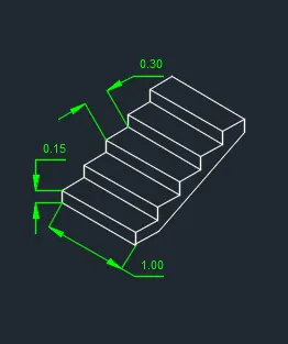
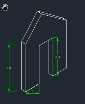
AIM6 :-To draw the isometric view of gable wall
Introduction :- To draw the isometric view of gable wall by using autocad
Procedure:-
- Type command DS in command box keep the isometric snap on and off the grid snap off make sure that earthing mode is on
- step 1 from the isometric drafting select the Y axis plane take the line command and create a line of 1 unit
- take the cursor to y-axis create a line with 2.42 unit
- take the cursor to minus x axis with the unit of 1
- take the cursor to minus y axis create a line with 2.42 unit
- take the cursor to minus x axis with the unit 1
- take the the cursor to left and create a line unit of 3
- take the cursor to right and create a line unit of 3.25
- step 2 from the isometric drafting in select the top isoplane
- next create the width of unit 0.3 from the isometric drafting select the right axis plane take the cursor to left and create a line unit of 3
- step 3 next create an inclined line by joining the top end of mid line
- next create a width 0.30
- step 4 copy the incline line specify the base point and copy to other Side
- next trim the extra line
Result :-