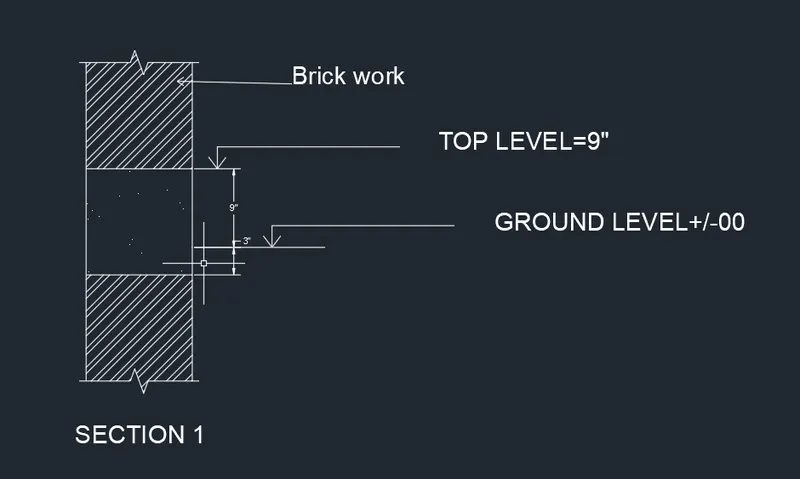
Creation of Column Schedule and Drawing Template using AutoCad
1) Aim : To create a column Schedule as shown in figure.
Procedure : Open AutoCAD
* In startup settings start from scratch select engineering(inches)
* Type un in command box and press enter. Change units type to engineering and precesion to 0.00 and insertion scale to inches.
* First open annotate in ribbon select table in that give no of datarows as 3 and columns as 12 set sell styles as data and each column height as 8" and manage text style as Roman.shx.
* Then type DT in command box and write information what we need in each column.
* To draw the daigrams of stirrups type rec in command box draw a rectangle and then type off in command box draw one offset inside the rectangle.
* Then draw small circles at top corners in rectangle ang tivr div in command box and make 3 parts and in each part draw two circels and draw lines on it.
* Then type tr in command box and trim unwanted lines.
Result :

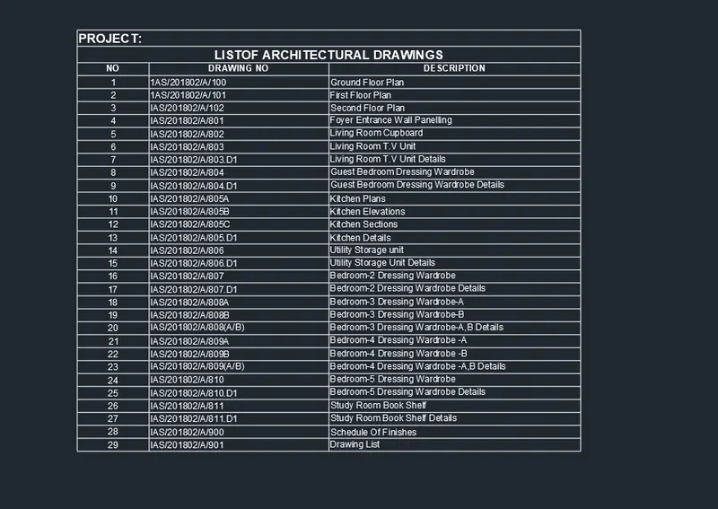
2) Aim : To create a Window Schedule as shown in figure.
Procedure : Open AutoCAD
* In startup settings start from scratch select engineering(inches)
* Type un in command box and press enter. Change units type to engineering and precesion to 0.00 and insertion scale to inches.
* First open annotate in ribbon select table in that give no of datarows as 4 and columns as 5 set sell styles as data .
* Then type DT in command box and write information what we need in each column.
Result :

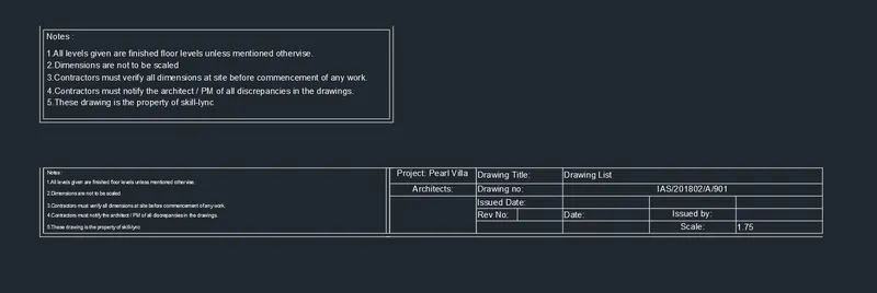
3) Aim : To create a Drawing tamplet as shown in figure.
Procedure : Open AutoCAD
* In startup settings start from scratch select engineering(inches)
* Type un in command box and press enter. Change units type to engineering and precesion to 0.00 and insertion scale to inches.
* Type rec in command box and draw a rectangle .then type DT in command box and write text inside the rectangle as shown in figure
* First open annotate in ribbon select table in that give no of datarows as 1 and columns as 6 set sell styles as data .
* Then type DT in command box and write information what we need in each column.a
* In first column merge the all rows as shown figure. and in all last two rows also we have merge.
Result :
4) Aim : To create a Drawing tamplet as shown in figure.
Procedure : Open AutoCAD
* In startup settings start from scratch select engineering(inches)
* Type un in command box and press enter. Change units type to engineering and precesion to 0.00 and insertion scale to inches.
* First open annotate in ribbon select table in that give no of datarows as 30 and columns as 3 select first row style as title second row style as title and remaing rows as data.
* Then write all information in side the each row like given in the figure.
Result :
5) Aim : To create Beam detail as shown in figure and providing text Whatever given.
Procedure : Open AutoCAD
* In startup settings start from scratch select engineering(inches)
* Type un in command box and press enter. Change units type to engineering and precesion to 0.00 and insertion scale to inches.
* Type rec in command box draw on rectangle and type div in command box and enter the number of divided segments as 3 and draw Horizontal lines at divided poits.
* Then select express tools in ribbon and select break line and draw the break lines at top and bottom of the rectangle.
* Then type bhatch in command box and select pattern as ANSI32 and give that hatch top and bottom blocks and in middle one give hatch as ACAD ISO0.
* Then type DT in command box give text height and write text as shown in figure. then typen dim in command box and give dimensions as shown in figure.
Result: