Creation of Column Schedule and Drawing Template using AutoCad
QUESTION NO. -1
ANSWER:
AIM:- Creation of Column Schedule and Drawing Template using AutoCad
PROCEDURE:-
STEP -1
SETTINGS - OPEN AUTOCAD
- SET DEFAULT SETTINGS - IMPERIAL UNIT (feet and inches)
- SELECT A TEMPLATE - ACCORDING TO DRAWINGS
- SELECT A WIZAED - ADVANCED SETUP
- UNITS - ENGINEERING , PRECISION -0.00
- ANGLE - DECIMAL DEGREES
- ANGLE MEASURE - ACCORDING TO PLAN
- ANGLE DIRECTION - COUNTER CLOCKWISE
- AREA - ACCORDING TO PLAN
- To create the table we use the line command and a rectanglular shape shown in the figure.
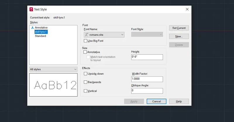
- In command bar type "ST" (for test stlye) than select the following options
Font name -- romans.shx
height -- 8"
justify -- left
Rotation angle -- 0 if needed change the agnle 90 degree or other
STEP -2
- take line command to draw a rectangle. divided the no. of parts of column and row using offset command.
- with help of line command draw lines to make written section part of drawing part
STEP -3
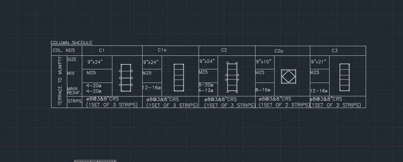
- draw coloum C1,C1a,C2,C2a,C3 with equale size and divided into same part for written data and drawing.
- Start writting first we write COLUMN SHECDULE" corner of the colum
STEP -4
- For symbol of diameter go to MTEXT and go to symbol option and choose the phai symbol copy and paste in the written place.
- we can use for extend the line we use the extend command .
STEP -5
- set all the Text according to the drawing.
- With the help of trim or erase command trim the all unwanted lines.
QUESTION NO. -2
STEP-1
- In command bar type "ST" (for test stlye) than select the following options
Font name -- romans.shx
height -- 8"
justify -- left
Rotation angle -- 0 if needed change the agnle 90 degree or other
STEP-2
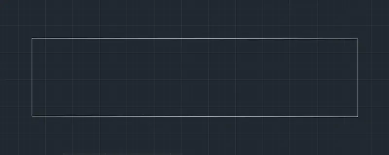
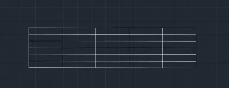
- To create the table we use the line command and a rectanglular shape shown in the figure.
STEP-3
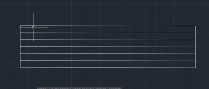
- take line command to draw a rectangle. divided the no. 6 row of th rectangle with same dimention using offset 2' command.
STEP-4
- take offset command divided the no. 5 column of the rectangle with same dimention using offset 12' command.
STEP-5
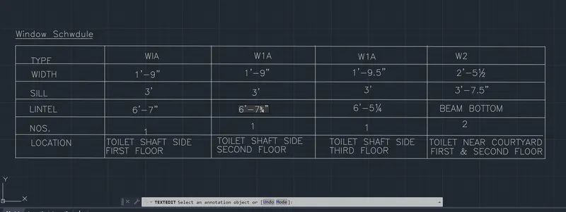
- Write in the row TYPE ,WIDTH, SILL , LINTEL, NOS, LOCATION in the first column.
- Write coloum W1A , W1A, W1A, W2 with equale size and divided into same part for written data and drawing.
- Start writting first we write WINDOW SHECDULE" corner of the column.
STEP -5
- For symbol of diameter go to MTEXT and go to symbol option and choose the fractional symbol copy and paste in the written place.
- we can use for extend the line we use the extend command .
- if needed extend the column select the part which part we want to extend and move the horizontal or vertical direction. according to need.
QUESTION NO. -3
Procedure:-
STEP-1
- In command bar type "ST" (for test stlye) than select the following options
Font name -- romans.shx
height -- 8"
justify -- left
Rotation angle -- 0 if needed change the agnle 90 degree or other
STEP-2
- with the help of line command draw construction horizontal line.
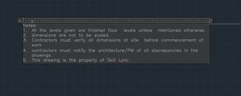
- than go to MTEXT(multiline text).
- select the paragraph with the help of cursor.
- and start the writting.
- GO to bullets option and select numbering bullet. and exit command
STEP-3
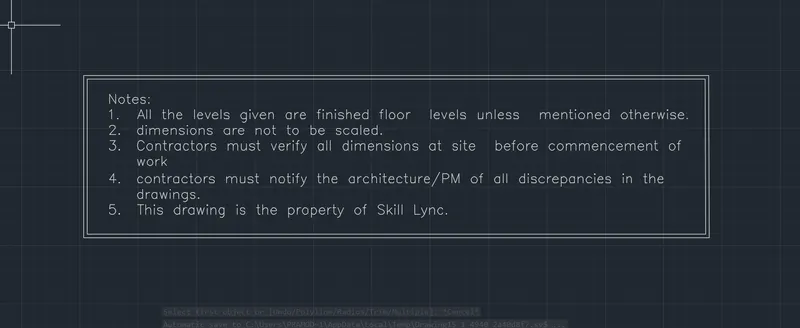
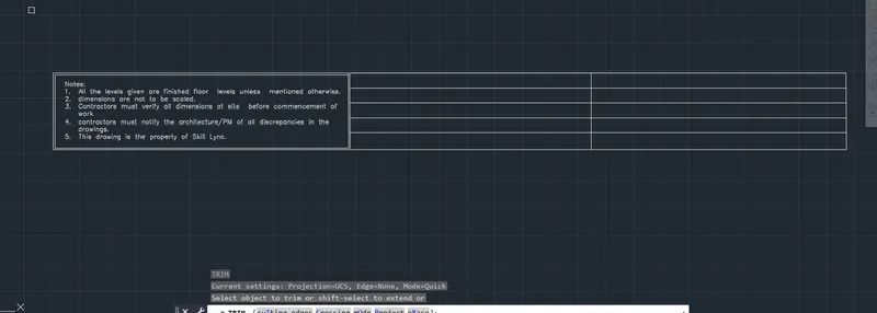
- with the help of line command draw a rectangle outside of the written content. for good elevation use 2" of offset outside this and connect corner with fillet.
STEP-4
- Draw second column using line command and make 2 column and 5 row with the offset command
STEP-5
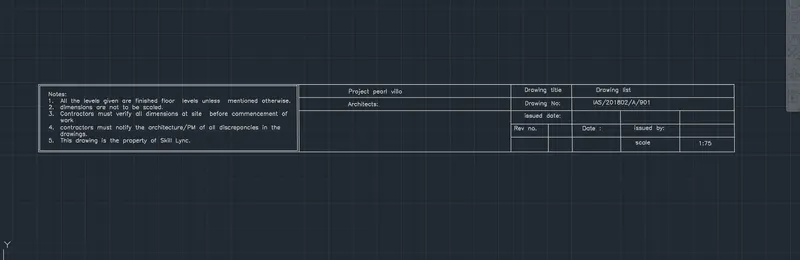
- Write all the written content with the help of dtext command at right place.
QUESTION NO. -4
STEP-1
- In command bar type "ST" (for test stlye) than select the following options
Font name -- romans.shx
height -- 8"
justify -- left
Rotation angle -- 0 if needed change the agnle 90 degree or other
STEP-2
- With the help of line command draw a contruction line horizontally and vertically.
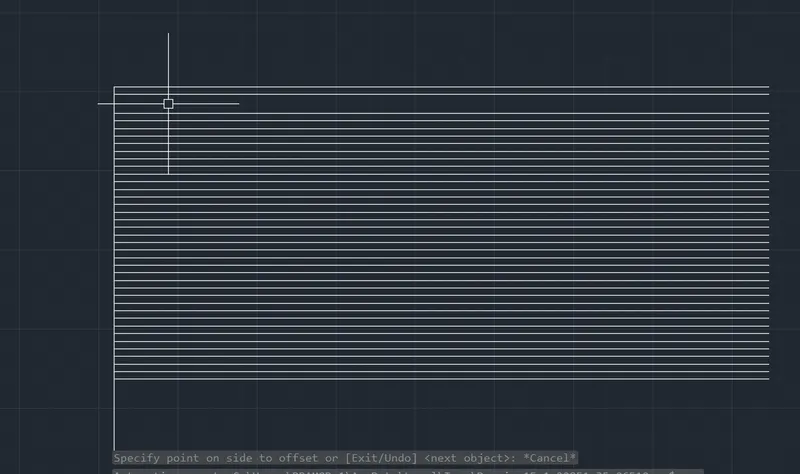
- with the center point of XL draw offset of 2' downword direction and another is 4' from the lastt offset.
- than make no. of 23 row with the help of offset command.
STEP-3
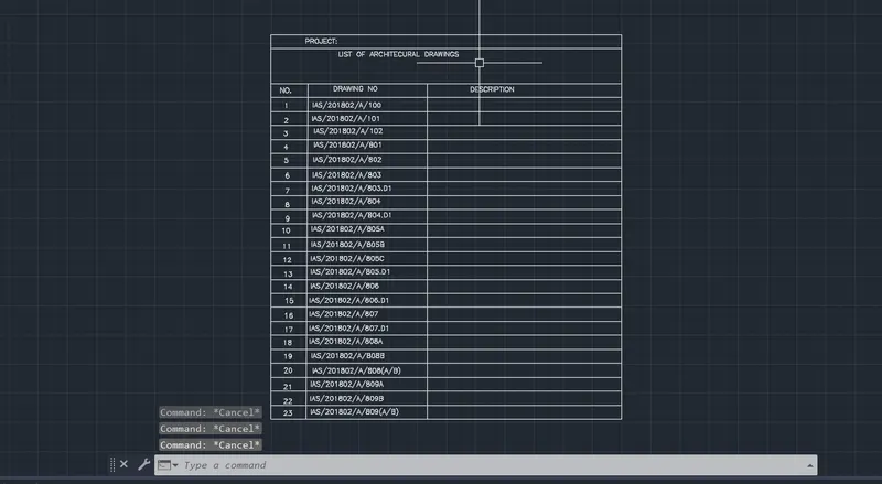
- Make three Columns 1st for no. , 2nd for Drawing No. , 3rd for Description according to written contents.
- Use DTEXT for text and Set the Size according to the written contents in the row and Column.
- Trim All the unwanted line using Trim Command.
STEP-4
- Write All the Written data at the particular Row and Column according to Attached file.
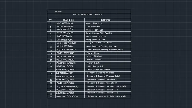
RESULT:
QUESTION NO. -5
STEP -1
IN THE COMMAND BAR SET UNIT ARCHITECTURAL (feet and inches )
- use line command to creat column. and make column ground level top level and brick work with the help of line trim and extend command.
- Also make Arrow Symbol with the help of line Command.
STEP -2
For text Style:
- In command bar type "ST" (for test stlye) than select the following options
Font name -- romans.shx
height -- 8"
justify -- left
Rotation angle -- 0 if needed change the agnle 90 degree or other
STEP -3
- Enter Dtext and write all the given dimntion and Text.
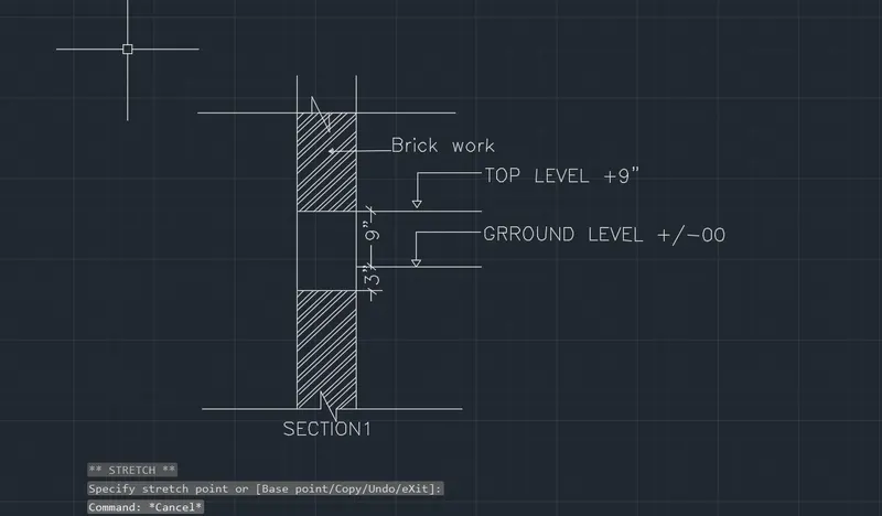
RESULT :
ALL THE GIVEN DRAWINGS , COLUMN SHECDULE ,DRAWINGS TEMPLATE ARE COMPLETED WITH THE PROPER DIMENTION AND DATA. AFTER MAKING THE DRAWING FINAL DRAWING SCREENSHOTS ARE ATTACHED WITH RESULTENT DRAWING .
RESULTENT DRAWING:
DRAWING NO.1
DRAWING NO.2
DRAWING NO.3
TABLE-1
TABLE-2
DRAWING NO. 4
DRAWING NO. 5