Creation of Column Schedule and Drawing Template using AutoCad
QUESTION-1:
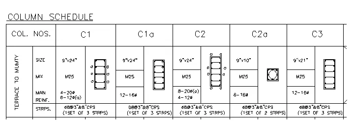
Create a Column as shown in the figure.
Note: Create a Column Schedule with the help of lines.Also ,insert text with the help of Dtext command or single line text.
Hint: Use font name :romans.shx: Height: 8",Justify: Left.
ANSWER:
AIM: To Creat a column schedule as shown in drawing by using autocad.
INTRODUCTION:
- We have to create a column schedule given in challenge by using various command with assuming dimension.
- The purpose of column schedule is a schedule which give details of column will be collected in construction for design purpose.
- From the above table :
- C1 column is provided with 6 bars of 12 mm dia and 4 bars of 20 mm dia 12 mm dia is mentioned as "a".
- Cla column is provided with 12 bars of 16 mm dia.
- C2 column is provided with 8 bar of 20 mm dia and 4 bars of 12 mm dia.
- C2a colum is provided with 12 bars of 16 mm dia.
- C3 column is provided with 12 bars of 16 mm dia.
- Lets assume column cover as 2"(approx 50mm).
PROCEDURE:
STEP-1:
- Create new drawing in autocad & set up limits.
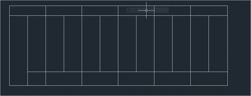
- Create a rectangle as per assumed size which depend upon size of colum and text.
- Type rec in command tab -Specify Dimension.
- By using line command and offset command divide rectangle into 5 part in x-direction and four parts in y-direction.
STEP-2:
- Type REC in command :REC.
- Specify corner point with dimension give length 9" and width 24" for rectangle
- Command offset (o).
- Give offset distance0.4"
- Select rectangle and in side of rectnagle.
- Create circle by using command.
- Select circle with diameter ,draw two circles of dia 0.787 & 0.472 inches.
- Select lines of first corner as tangent and type radius 0.39"
- Mirror the circle using MI command opposide & vertical side with reference line.
- Similarly follow same procedure for remaining column making.
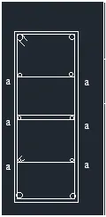
xi.By using trim the extension lines.
STEP-3:
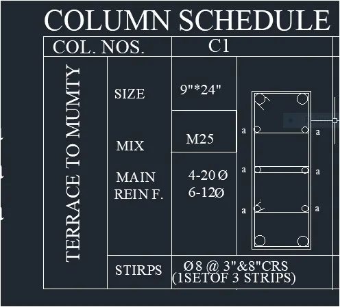
- Do same procedure to create column detail drawing.
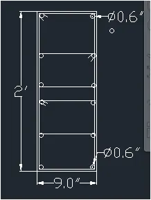
- For C1a colum,circle with diameter 0.6 and divide into 5 lines.
STEP-4:
- Do same procedure to create column detail drawing.
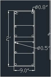
- For C2 column ,circle with dia 0.8"and 0.5" at given places.
STEP-5:
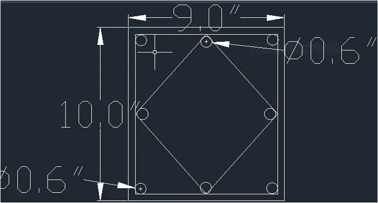
- For C2a make a rectangle of 10"*9" and circle of dia 0.6"
STEP-6:
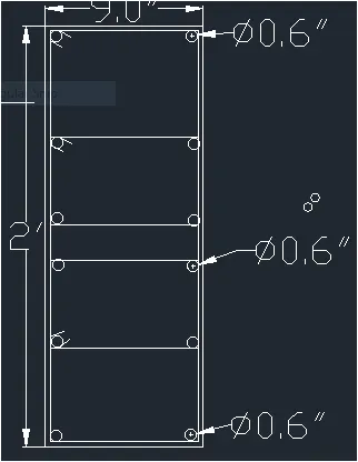
- Making C3 is similar to C1 column but rebar dia is 0.6".
STEP-7:
- Enter the data of column details.
- Select column drafted and move to required cell.
- Using Font Romans & text size8".
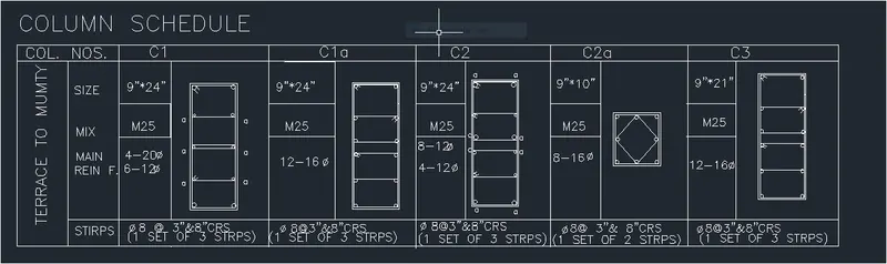
RESULT:
QUESTION-2:
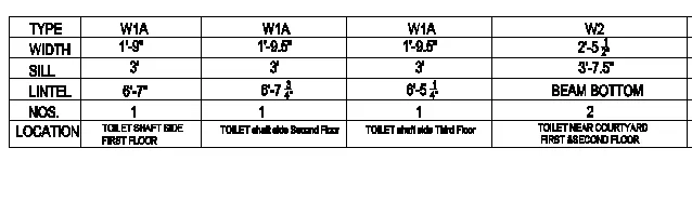
Create a Window Schedule as shown in the figure.
WINDOW SCHEDULE:
ANSWER:
AIM: To create a Window Schedule,and to draw the detail of windows for construction purpose.
INTRODUCTION:
- The window schedule and do draw the details of the windows in construction can be collected in the table form.
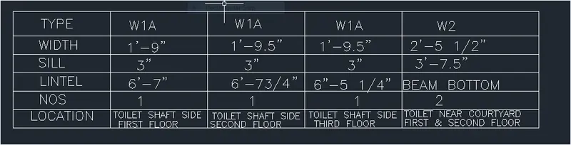
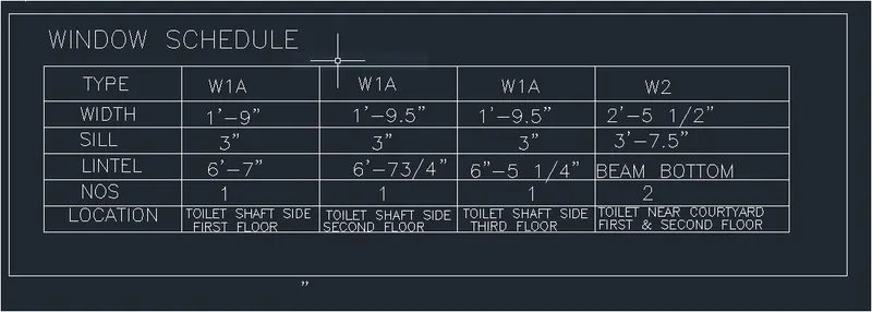
- Above table consist of details of different windows.
- Details holds its width,sill and lintel with number of windows of that type and location of placing windows.
PROCEDURE:
STEP-1:
- First of all we have to open autocad and set limits and units.
- Next we have to draw table using line command or by wirting table using line command or by writing table in command tab.
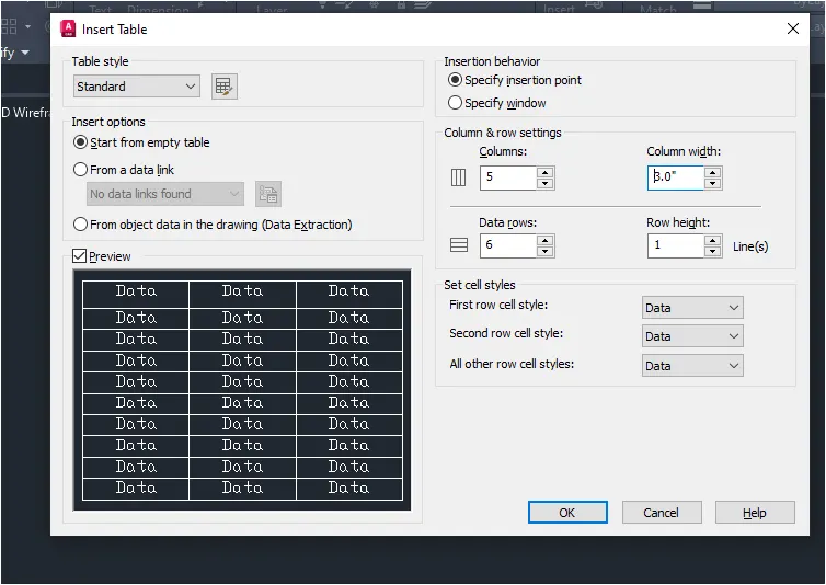
- Screenshot 1: Creating table to draw out window schedule.
STEP-2:
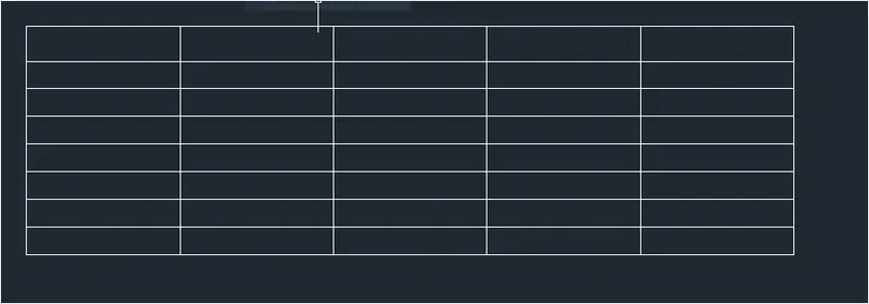
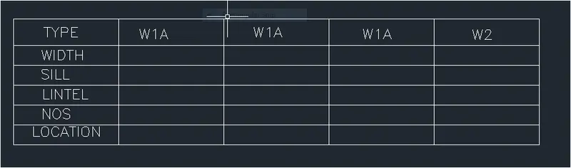
- Screenshot-2: Created table we can add or delet row/column.
STEP-3:
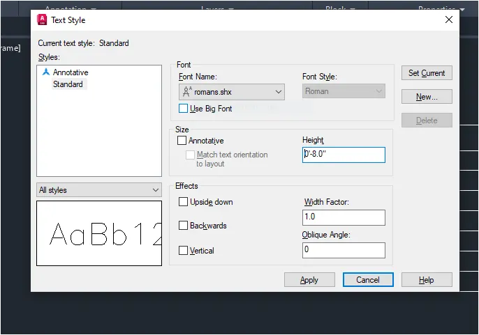
- Screenshot-3: We have selected font Romans & text height as per given.
STEP-4:
- Screenshot-4: We are adding notes/information as per given in question.
STEP-5:
- Screenshot-5: We write all the information given in window create so window schedule is created.
RESULT:
QUESTION-3:
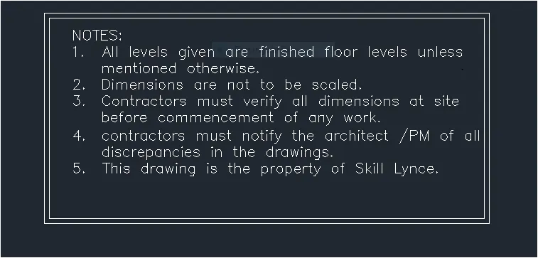
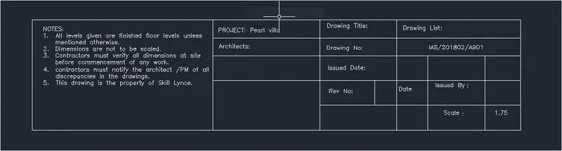
Create the Drawing Template as shown in the figure;<Use the Notes as in the Figure>
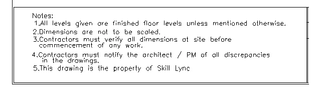

ANSWER:
AIM: To Create the drawing template as shown in the figure of Note.
INTRODUCTION:
- In order to create a drawing template using Dtext or text command to write text.
- Drawing template files are drawings that stors styles,settings,layers and layouts in a drawing including title blocks.
- Drawing template depends on type of drawing provided like it varies for Architecural,Electrical,Water supply etc.
- It holds the notes which required to be followed during construction.
- Also holds details like project name.adress ,date,architect name, company name etc.
- Like making a plot drafting are placed inside drawing template.
COMMANDS USED:
- Limits.
- Text.
- Line.
PROCEDURE:
STEP-1:
- Select table from annotation tool bar and set text style as time new roman with text height and justification as 1" and middle center.
- Set rows as 2 and column 1 for middle table portion.
- Repeat the table command, set rows-4 and column 3 andplace next to previous column.
- Now draw a rectangle of same height as table with certain distance.

STEP-2:
- Use multiline text command for Notes content in left box with text height -3".
- Enter the data in cells.
- Select cell to be merged in right table.
RESULT:
QUESTION-4:
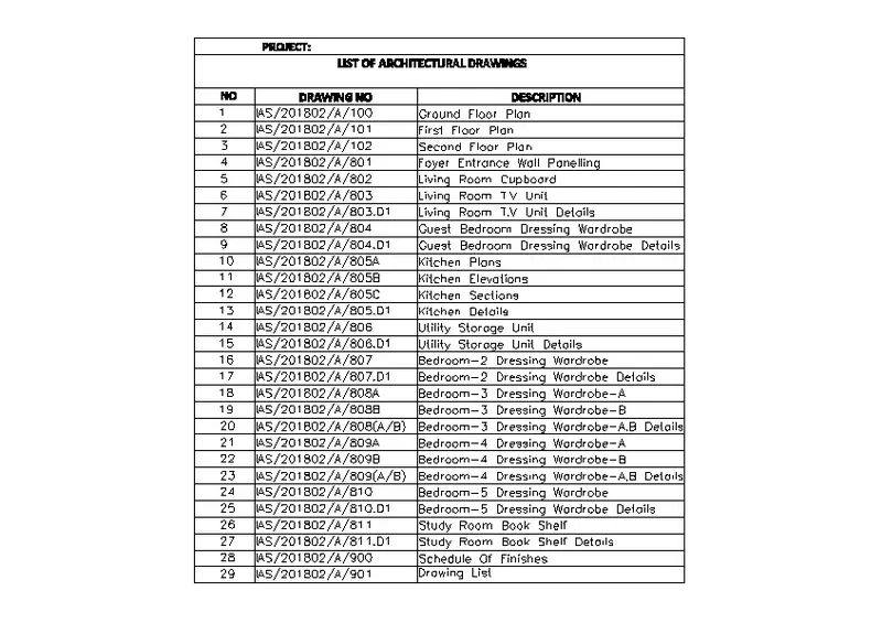
Create the drawing templateas shown in the figure.
ANSWER:
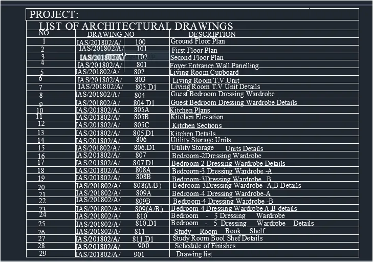
AIM: To craete the list of drawing schedule as shown in figure.
INTRODUCTION:
- A schedule of drawing is an itemised list of drawings required for a building project .
- It can be included as part of an invitation to tender ,or may be prepared as part of adesign management plan.
- A schedule of drawings required may include all the drawings required for a project or an larger ,more complex project,it may be specifically prepared for a certain displine.
PROCEDURE:
STEP-1:
- First we have to open Autocad and set limits and units.
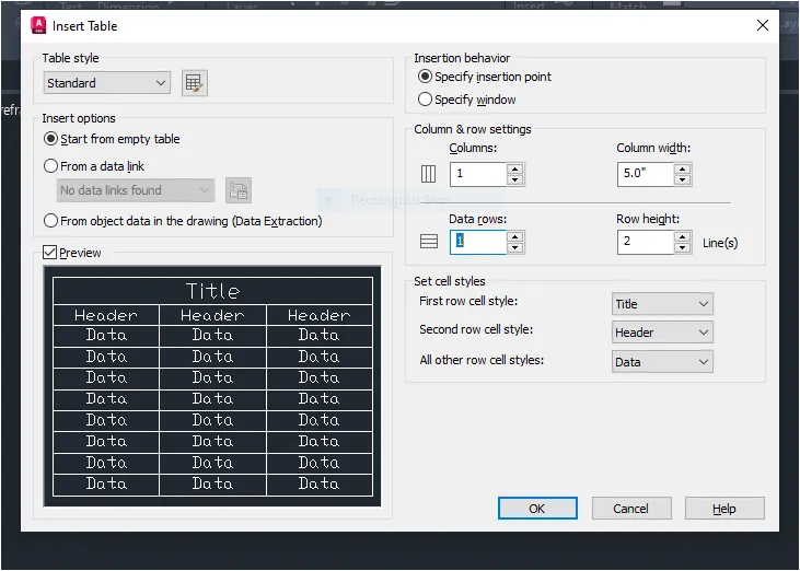
- Then we have to enter table in command for creating table.
- After entering table command table setting screen will be displayed as shown in screenshot 1.

STEP-2:
- Screenshot-2: Creating table.
STEP-3:
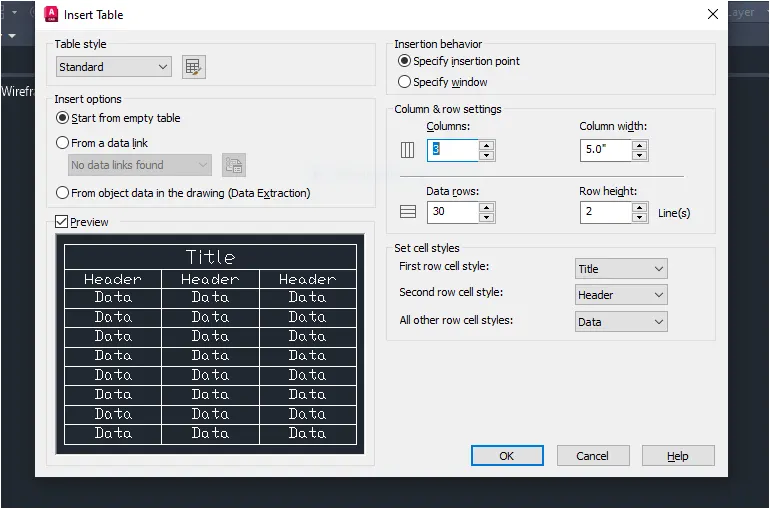
- Screenshot-3 We have customized table as per required rows and column.
STEP-4:
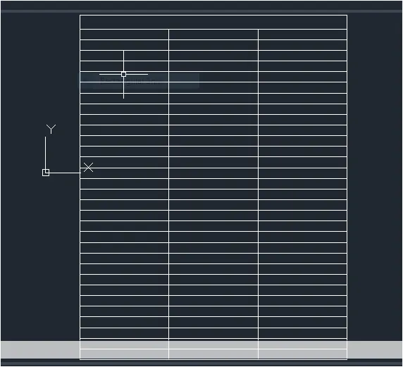
- Screenshot-4: We have created table.
STEP-5:
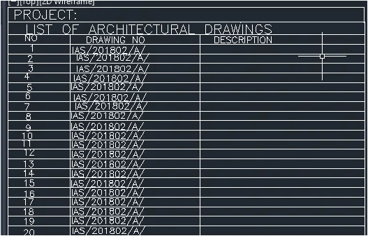
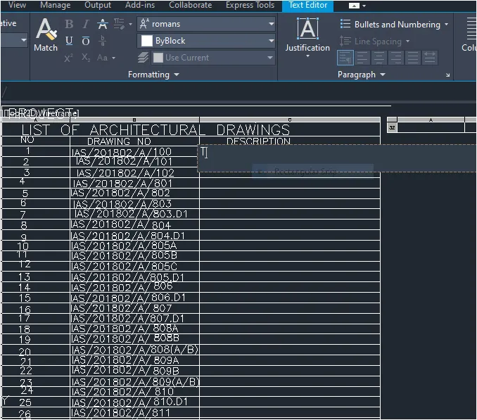
- Screenshot-5 We have started to write drawing schedule with Roman font & height.
STEP-6:
- Screenshot-6: We justify it to left.
STEP-7:
- Screenshot-7: All the drawing detail are feeded.
RESULT:
QUESTION-5:
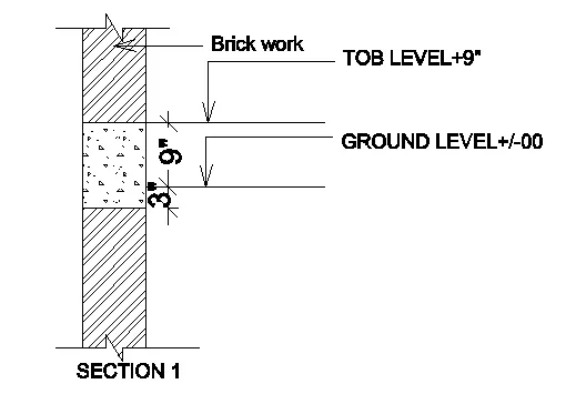
Create the beam detail as shown in the figure and provide text wherever given.
ANSWER:
AIM: To create a beam detail given in figure.
INTRODUCTION:
- A beam is a structural element that primarily resist load applied laterally to the beam's axis.
- ITS made of deflection is primarily by bending.
- The loads applied to the beam result in reaction forces at the beams support points.
- The total effect of all the forces acting on the beam is to produce shear forces and bending moments within the beams.
COMMANDS USED:
- Limits.
- Line.
- Dimlinear.
- Trim.
- Offset.
PROCEDURE:
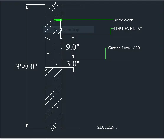
Assumed dimensions for beam detail.
STEP-1:
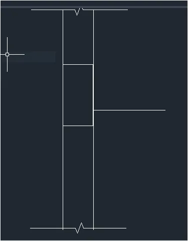
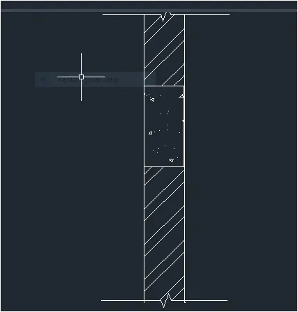
- Make to parallel lines 45" long at a distance of 6" from each other.
- Using the breakline at top and bottom
- Make the horizontally lines with 9" distance and draw a line horizontally forward from that distance,that line we call the top level.
- Next we have to put the dimensions for the ground level,its distance is 3"
STEP-2:
- Then next we have to provide the texts fr the particular parts,they are brick work,lable as top level and ground level.
- Next we have to use Hatch command to hatch the different parts in diagram.
RESULT: