Creation of Column Schedule and Drawing Template using AutoCad
- Following are the Commands used in this challenge:-
- Line 'L'
- Copy 'CO' or 'CP'
- PolyLine 'PL'
- Trim 'TR'
- Offset 'O'
- Text
- Dimension 'DIM'
- Dimstyle 'D'
- MATCHPROP 'MA'
- Move 'M'
- Mirror 'MI'
- Fillet 'F'
- Erase 'E'
- Rotate
- PTYPE
- POINT
- CIRCLE
- RECTANGLE
- units
- Hatch
- Array
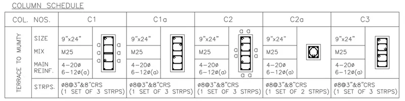
Q1) Create a column schedule as shown in the figure.
Aim: To create the column schedule using the necessary commands
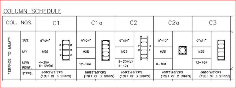
Introduction: Structural columns are identified in a column schedule by intersecting grid lines and by their top and bottom constraints and offsets. They are placed into the column schedules according to these identifications. Video: Create Graphical Column Schedules.
Page Setup:
Open new page
Select Architectural
Precision as 0-0 1/256” and Apply
PROCEDURE
1. Convert the diameter of the bars into inches. The following table contains conversion (Divide by 25.1`
| Values in mm | Values in Inches |
| 20 | 0.7874 |
| 16 | 0.6299 |
| 12 | 0.4725 |
| 8 | 0.3150 |
Instructions for steps 2→6:
A. The dimensions for the bars on the left are the same as that of the bars on the right.
B. The longitudinal and stirrups are hatched with a white solid fill.
2. Make the column C1 as shown.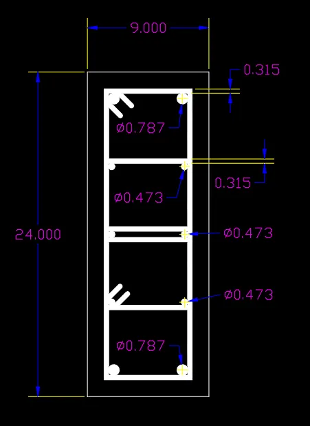
3. Make the column C1a as shown.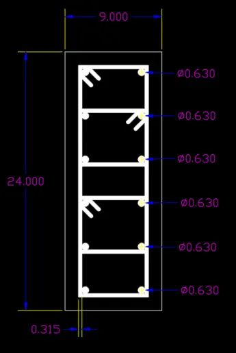
4. Make the column C2 as shown.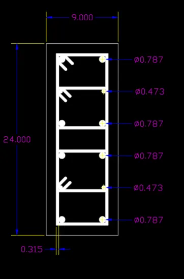
5. Make column C2a as shown.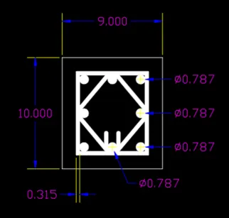
6. Make the column 3 as shown.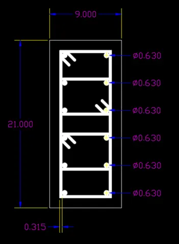
7. Make this table as shown.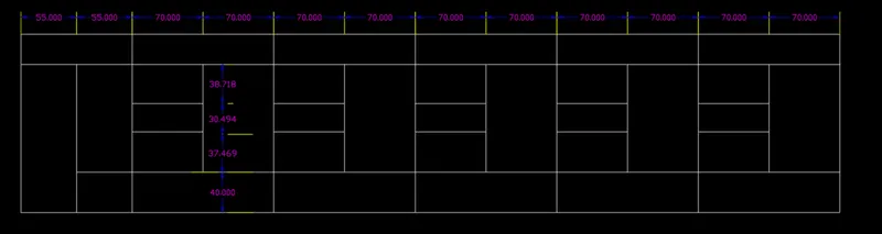
8. Make a new text style with the font - romans.shx and height 8"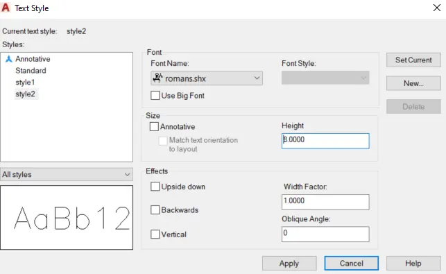
9. Using this text style, fill the table using single line text as shown. (Rotate "Terrace to mumty" by 90 degrees)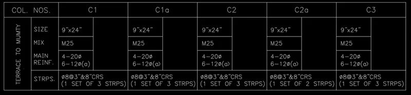
10. Scale the columns made in steps 3-7 by a factor of 3.2 in order to fit them in their respective place.
11. Move the columns one by one to their respective places.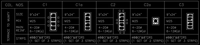
12. Give the heading Column Schedule using multi-line text and underline it.
RESULT
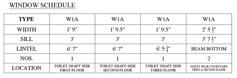
Q2) Create a window schedule as shown in the figures:

Aim: To Create a window schedule in AutoCAD
Introduction: A tabulation, usually on a blueprint or in specifications, which lists all windows required on a construction job, indicating the sizes, number of lights, types, locations, and special requirements.
To Create this schedule table and Text commands are used
Page Setup:
Open new page
Select Architectural
Precision as 0-0 1/256”
Apply okay
PROCEDURE
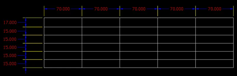
1. Make the following table.
2. Using multiline, fill in the following data with justification middle center MC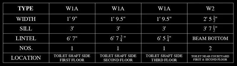
3. Using multiline, give the heading "Window Schedule" and underline it.
RESULT
Q3) . Create the drawing templates as shown in the figure


Aim: To Create a window schedule in AutoCAD
Introduction: Templates are stencils that allows you to draw specific symbols and shapes that you use repeatedly in a design.
To create this template Line, Trim, Text , Multitext commands are used
Page Setup:
Open new page
Select Engineering
Precision as 0’-0”
Page limits as 150’ x 100’
Apply okay
PROCEDURE
1. Make the following table.
2. Using multitext, type the following as shown and place it in the first column. (Height = 2.5" and Font = Arial)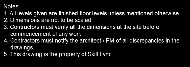
3. Type the following in rest of the cells as shown using multitext: (Make a vertical line after Rev. No:) (Text height = 2.5" and Font = Arial)
RESULT

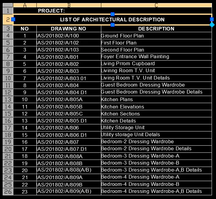
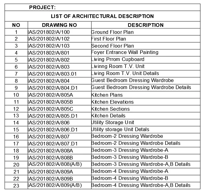
Q4) Create the list of drawing schedule as shown in the figure:
Aim: To Create a drawing schedule in AutoCAD

Introduction: A schedule of drawings is an itemised list of drawings required for a building project. It can be included as part of an invitation to tender or may be prepared as part of a design management plan. ... Drawing types and purposes. Drawing numbers and revisions.
To create this template Table and Text commands are used
Page Setup:
Open new page
Select Engineering
Precision as 0’-0”
Apply okay
PROCEDURE
1. Open the table command.
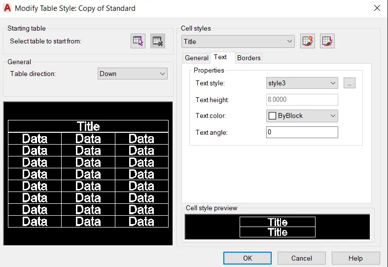
2. Create a new table style by selecting the required text style, text height, etc. for all the cell styles.
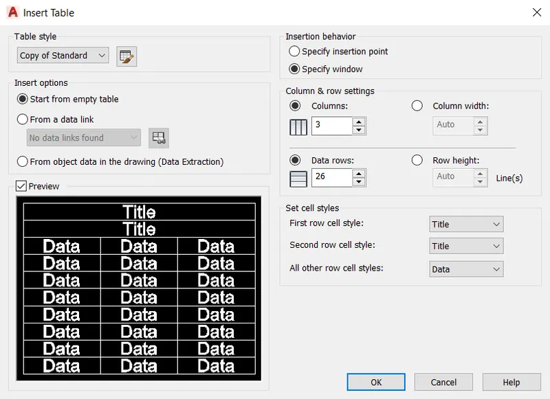
3. Enter the number of rows and columns, set the cell styles and using any insertion behaviour, insert the table.
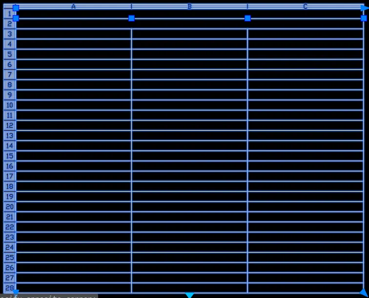
4. Adjust the size of rows and columns.
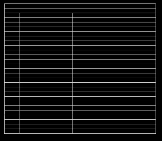
5. Enter the data.
6. Make the contents of title and header rows as Bold.
7. Give the required justification to the cells and adjust the cell sizes if required.
RESULT
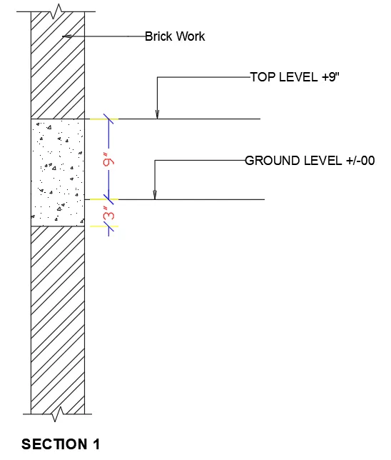
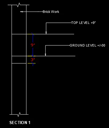
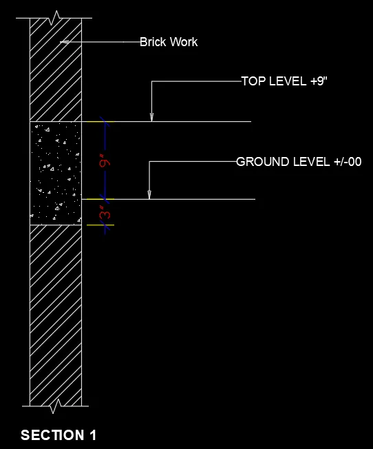
Q5) Create the beam detail as shown in the figure and provide text for Top level and Ground level as per required
Aim: To Create a beam in the AutoCAD

Introduction:
To create this template using line, text, hatch, trim, offset, ortho and dimension commands
Page Setup:
Open new page
Select Engineering
Precision as 0’-0”
Apply okay
PROCEDURE
1. Make two parallel lines 45" long at a distance of 6" from each other.
2. Using the breakline command, make a breakline at the top and bottom.
3. Make the horizontal lines as shown in fig B.
A. 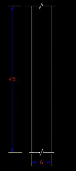 B.
B. 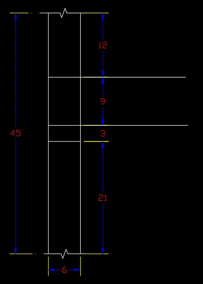
4. Give the required labeling using leader and multitext.
5. Modify the dimension to match with that in the question. (Arrowheads, suffix ("), etc.)
6. Give the hatching of brickwork and concrete as shown.
RESULT