Creation of Column Schedule and Drawing Template using AutoCad
Challenges – Week 5
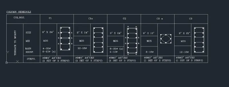
- Create a column schedule as shown in the figure.
Note: Create a column schedule with the help of lines. Also, insert text with the help of Dtext command or Single Line text.
Hint: Use font name: romans.shx; Height: 8”, Justify: Left

AIM:
Creating column schedule with the help lines Also , insert text with the help of Dtext command or Single line text.
Introduction :
Various command used while Sketching:
- Line command
- Circle command
- Trim
- Circle
- DTEXT or TEXT
- Rectangle
- Copy command
- Dimension
- Zoom command
- Trim command
- Unit command
- Fillet command
- Extant command
PROCEDURE :
STEP 1 :
- GO to START MENU ,select AutoCAD 2018.
- Enter “UNITS” command in the command tab.
- Open “ Drawing units “ dialogue box , Type as “ENGINEERING” and precision as 00
- Then click units scale to “ INCHES”
- Click “OK”.
- Enter “ LIM MAX” command in the command tab.
- Enter new value for Lim max as 200’
- Enter “zoom” command in the command box.
- Enter “All” command in the command box.
- Enter “LIMITS” command in the command box.
- Specify lower left corner as 0’,0’
- Specify lower right corner as 200’,200’.
- Enter “zoom “ command in the command box.
- Enter “ALL” command in the command box.
STEP 2:
- Enter “XLine “ command in the command box.
- Click “V” in the command box.
- Click “Enter”.
- Enter “XLINE” command in the command box.
- Click “H” in the command Box.
- Click “ENTER” .
- Enter the “OFFSET “ command in the command box.
- Click privies “vertical line “ give value of 84’ in the X – direction
- Enter “ OFFSET “ command in the command box.
- Click privies’ “Horizontal line” and give value of 21’ in the Y -direction.
- Click “ENTER” . than “ESC”.
- Enter “TRIM” Command in the command box.
- Erase the unnecessary line in the box.
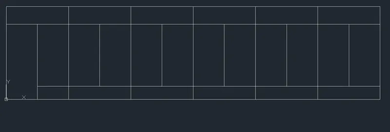
- ENTER “ST “command in the command box.
- U will get dialoge box.
- Click font name “shx”
- Then click “ TEXT HIGHT” give value of 0’-8.0”
- Then “SET CURRENT” .
- Click “OK” .
- Enter “DTEXT or TEXT “ command in the command box.
- Enter “select place”
- Click “ENTER”
- Give “TEXT ANGLE AS 0” click “ENTER”.
- Than “ START writing” as per the question .
- Enter “DTEXT or TEXT “ command in the command box.
- In the “TERRANCE TO MUMTY” only u can give angle as 90
STEPS FOR DRAWING THE COLUMN :
- The size of column C1 is 9”x24” , create a rectangle size of 9”x24” that is 2’
- Enter “Offset” command in the command box.
- Enter value of offset is 5 a smaller rectangle in the original rectangle will be drawn.
- Enter “DIV” command in the command
- Now dived line 4 parts by dived tool
- Draw the lines of division in the inside of rectangle
- Enter “FILLET” command in the command box.
- Fillet the edges as radius and enter the radius as 5
- Enter “CIRCLE” command in the command box.
- Enter “ TAN TAN RADIUS “ click two point .
- Draw the circle where the geometry is divided in parts
- Enter “ HATCH “ command in the command
- Go to “ home tap “ select SOILD AND COLOR white
- Fille the circles with white colors that is reinforcement bar.
- Draw the columns C1, C2, C2a, C3 in the same manner .
RESULT :
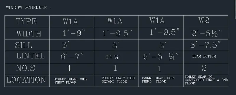
- Create a window schedule as shown in the figures:
Window Schedule:

AIM:
To Creating a windows schedule .
Introduction :
Various command used while Sketching:
- Line command
- Trim
- DTEXT or TEXT
- Rectangle
- Copy command
- Dimension
- Zoom command
- Trim command
- Unit command
- Fillet command
- Extant command
Introduction :
Various command used while Sketching:
- Line command
- Circle command
- Trim
- Circle
- DTEXT or TEXT
- Rectangle
- Copy command
- Dimension
- Zoom command
- Trim command
- Unit command
- Fillet command
- Extant command
PROCEDURE :
STEP 1 :
- GO to START MENU ,select AutoCAD 2018.
- Enter “UNITS” command in the command tab.
- Open “ Drawing units “ dialogue box , Type as “ENGINEERING” and precision as 00
- Then click units scale to “ INCHES”
- Click “OK”.
- Enter “ LIM MAX” command in the command tab.
- Enter new value for Lim max as 100’
- Enter “zoom” command in the command box.
- Enter “All” command in the command box.
- Enter “LIMITS” command in the command box.
- Specify lower left corner as 0’,0’
- Specify lower right corner as 100’100’
- Enter “zoom “ command in the command box.
- Enter “ALL” command in the command box.
STEP 2:
- Enter “XLine “ command in the command box.
- Click “V” in the command box.
- Click “Enter”.
- Enter “XLINE” command in the command box.
- Click “H” in the command Box.
- Click “ENTER” .
- Enter the “OFFSET “ command in the command box.
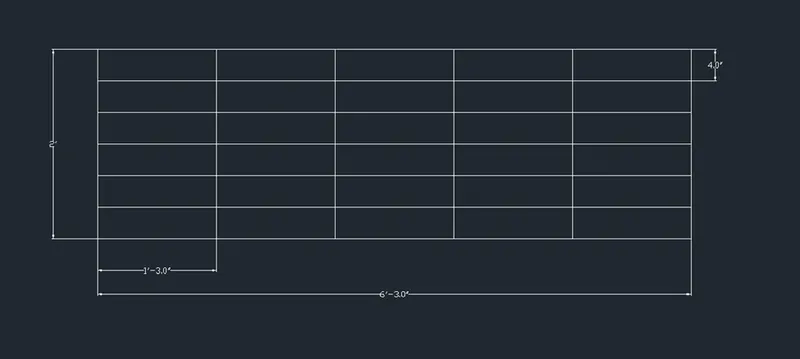
- Click privies “vertical line “ give value of 6’-3” in the X – direction
- Enter “ OFFSET “ command in the command box.
- Click privies’ “Horizontal line” and give value of 2’ in the Y -direction.
- Click “ENTER” . than “ESC”.
- Enter “offset “ command in the command box.
- Give value of 1’-3” between for each column in vertical line
- Enter “offset “ command in the command box.
- Give value of 4” between for each column horizontal line
- Enter “TRIM” Command in the command box.
- Erase the unnecessary line in the box.
- ENTER “ST “command in the command box.
- U will get dialoge box.
- Click font name “shx”
- Then click “ TEXT HIGHT” give value of 5” to 3”
- Then “SET CURRENT” .
- Click “OK” .
- Enter “DTEXT or TEXT “ command in the command box.
- Enter “select place”
- Click “ENTER”
- Give “TEXT ANGLE AS 0” click “ENTER”.
- Than “ START writing” as per the question .
RESULT :
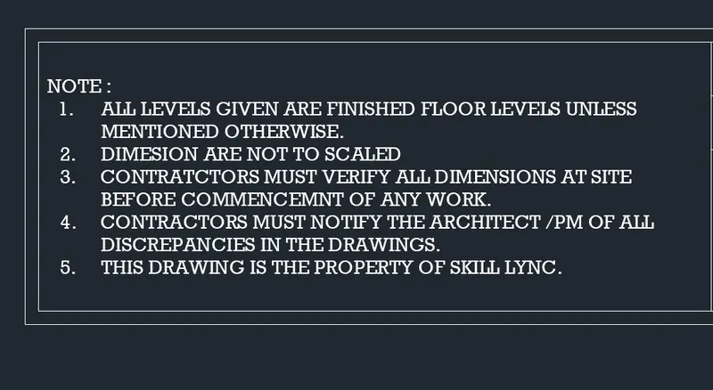
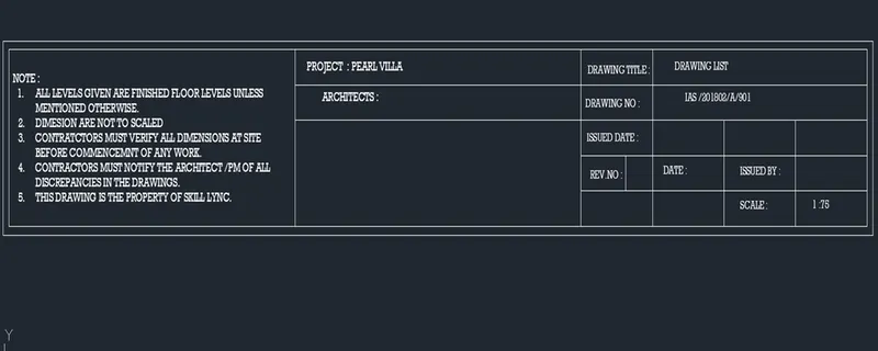
- Create the drawing template as shown in the figure:< Use the Notes as in the figure>


AIM:
To create the drawing template
Introduction :
Various command used while Sketching:
- Line command
- Trim
- DTEXT or TEXT
- Rectangle
- Copy command
- Dimension
- Zoom command
- Trim command
- Unit command
- Fillet command
- Extant command
PROCEDURE :
STEP 1 :
- GO to START MENU ,select AutoCAD 2018.
- Enter “UNITS” command in the command tab.
- Open “ Drawing units “ dialogue box , Type as “ENGINEERING” and precision as 00
- Then click units scale to “ INCHES”
- Click “OK”.
- Enter “ LIM MAX” command in the command tab.
- Enter new value for Lim max as 150’
- Enter “zoom” command in the command box.
- Enter “All” command in the command box.
- Enter “LIMITS” command in the command box.
- Specify lower left corner as 0’,0’
- Specify lower right corner as 150’150’
- Enter “zoom “ command in the command box.
- Enter “ALL” command in the command box.
STEP 2:
- Enter “XLine “ command in the command box.
- Click “V” in the command box.
- Click “Enter”.
- Enter “XLINE” command in the command box.
- Click “H” in the command Box.
- Click “ENTER” .
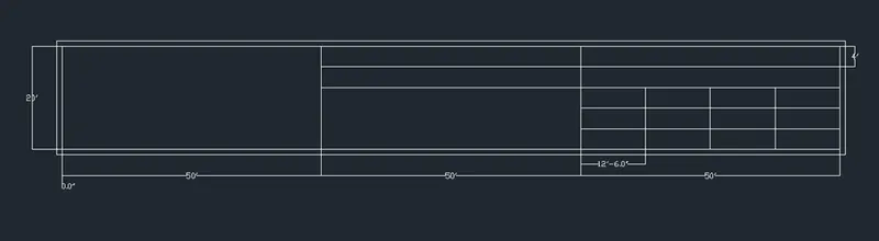
- Enter the “OFFSET “ command in the command box.
- Click privies “vertical line “ give value of 150’ in the X – direction
- Enter “ OFFSET “ command in the command box.
- Click privies’ “Horizontal line” and give value of 20’ in the Y -direction.
- Click “ENTER” . than “ESC”.
- Enter “offset “ command in the command box.
- Give value of 50’ between for each column in vertical line
- Enter “offset “ command in the command box.
- Give value of 4” between for each column horizontal line in the last table .
- Enter “offset “ command in the command box.
- Give value of 12’-6’ between for each column vertical line in the last table
- Enter “TRIM” Command in the command box.
- Erase the unnecessary line in the box.
- ENTER “ST “command in the command box.
- U will get dialoge box.
- Enter font name “ROCKWELL”
- Text Hight as 5” to 11.5” in the box
- Enter “MTEXT “ command in the command box.
- Text angle as 0 and start writing as per the question.
RESULT :
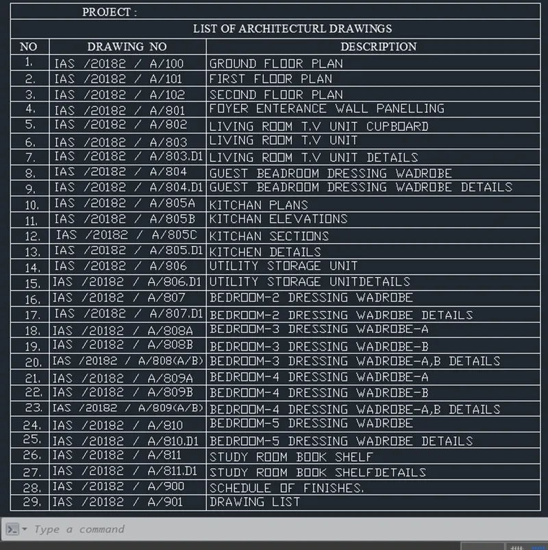
4. Create the list of drawing schedule as shown in the figure:

AIM:
To Create the list of drawing schedule
Introduction :
Various command used while Sketching:
- Line command
- Trim
- DTEXT or TEXT
- Rectangle
- Copy command
- Dimension
- Zoom command
- Trim command
- Unit command
- Fillet command
- Extant command
PROCEDURE :
STEP 1 :
- GO to START MENU ,select AutoCAD 2018.
- Enter “UNITS” command in the command tab.
- Open “ Drawing units “ dialogue box , Type as “ENGINEERING” and precision as 00
- Then click units scale to “ INCHES”
- Click “OK”.
- Enter “ LIM MAX” command in the command tab.
- Enter new value for Lim max as 200’
- Enter “zoom” command in the command box.
- Enter “All” command in the command box.
- Enter “LIMITS” command in the command box.
- Specify lower left corner as 0’,0’
- Specify lower right corner as 200’,200’.
- Enter “zoom “ command in the command box.
- Enter “ALL” command in the command box.
STEP 2:
- Enter “XLine “ command in the command box.
- Click “V” in the command box.
- Click “Enter”.
- Enter “XLINE” command in the command box.
- Click “H” in the command Box.
- Click “ENTER” .
- Enter the “OFFSET “ command in the command box.
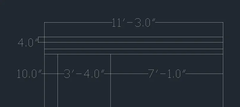
- Click privies “vertical line “ give value of 11’-3” in the X – direction
- Enter the “OFFSET “ command in the command box.
- Click privies “vertical line “ give value of 10” in the X – direction
- Enter the “OFFSET “ command in the command box.
- Click privies “vertical line “ give value of 3’-4” in the X – direction
- Enter “ OFFSET “ command in the command box.
- Click privies’ “Horizontal line” and give value of 4” in the Y -direction.
- U can create more than 31 columns in side of the box.
- Click “ENTER” . than “ESC”.
- Enter “TRIM” Command in the command box.
- Erase the unnecessary line in the box.
- . ENTER “ST “command in the command box.
- U will get dialoge box.
- Click font name “ANNOTATIVE”
- Then click “ TEXT HIGHT” give value of 5” to 2.5”
- Then “SET CURRENT” .
- Click “OK” .
- Enter “DTEXT or TEXT “ command in the command box.
- Enter “select place”
- Click “ENTER”
- Give “TEXT ANGLE AS 0” click “ENTER”.
- Than “ START writing” as per the question .
- In this table give some text style as “VARIES”.
- Create a template as per the figure.
RESULT :
- Create the Beam detail as shown in the figure and provide text wherever given.

AIM:
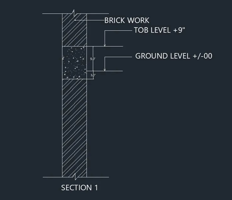
To Creating a beam details as shown in the figure and provided text whatever given.
Introduction :
Various command used while Sketching:
- Line command
- Trim
- DTEXT or TEXT
- Rectangle
- Copy command
- Dimension
- Zoom command
- Trim command
- Unit command
- Fillet command
- Extant command
PROCEDURE :
STEP 1 :
- GO to START MENU ,select AutoCAD 2018.
- Enter “UNITS” command in the command tab.
- Open “ Drawing units “ dialogue box , Type as “ENGINEERING” and precision as 00
- Then click units scale to “ INCHES”
- Click “OK”.
- Enter “ LIM MAX” command in the command tab.
- Enter new value for Lim max as 100’
- Enter “zoom” command in the command box.
- Enter “All” command in the command box.
- Enter “LIMITS” command in the command box.
- Specify lower left corner as 0’,0’
- Specify lower right corner as 100’100’
- Enter “zoom “ command in the command box.
- Enter “ALL” command in the command box.
STEP 2:
- Enter “XLine “ command in the command box.
- Click “V” in the command box.
- Click “Enter”.
- Enter “XLINE” command in the command box.
- Click “H” in the command Box.
- Click “ENTER” .
- Enter the “OFFSET “ command in the command box.
- Click privies “vertical line “ give value of0” in the X – direction
- Enter “ LINE “ command in the command box.
- Close the top and bottom space
- Click “ENTER” . than “ESC”.
- Enter “LINE “ command in the command box.
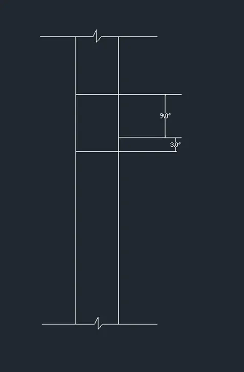
- Create horizontal line in the beam value of 9”
- Form the previse line value of 3” as ground level
- Click “ENTER “ . then “close”
- Enter “Line” command in the command box.
- Create line from the ground level , the value of 9”
- Create like rectangular box.
- Click “Enter” then “Close “
- Enter “TRIM” Command in the command box.
- Erase the unnecessary line in the box.
STEP 3:
- Click the place where you want concrete
- Enter “HATCH “ command in the command box.
- Right click the mouse , will get the option
- Click “HATCH EDIT “
- Go to the dialoge box .
- Click “swatch “ and will get “HATCH PATTRN PALETTE”
- Click “AR-CONC “ in the dialoge box
- Click “OK”.
- Change the “scale “ as per the drawing .
- I given concrete scale of 5
- Click “OK”.
- Enter “DTEXT or TEXT “ command in the command box.
- Click the place as per the picture
- Give “TEXT HEIGHT AS 2.0” .
- Give “TEXT ANGLE AS 0”
- If you want to the change the text style
- Go to home tap
- Click “Annotate” and click “STANDARD “
- Click “ Manage text style “
- Change the text style asper your choice
- Enter “D” command in the command box.
- U will get “DIMENSION STYLE MANAGER “ dialoge box
- Go to the “MODIFY” option
- Go to the “TEXT “ option
- Click “TEXT HIGHT AS 0.8”
- Go to the “LINE “ option
- Click “Baseline spacing “ value as 0.8”
- Click “DIMLINER “ in the command box.
- Click line , where you want to see the dimension
- Verify the dimension as the drawing
- Create beam as the drawing given figure
RESULT :
RESULT for Column Schedule and Drawing Template using AutoCad :
1.column schedule
2.window schedule
3. create the drawing template :
4.drawing schedule :
5.Create the Beam :