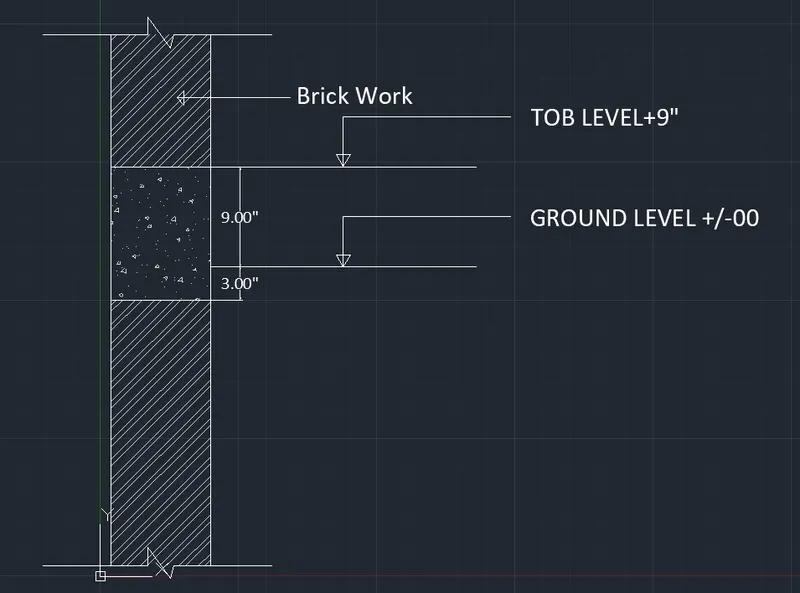
Creation of Column Schedule and Drawing Template using AutoCad
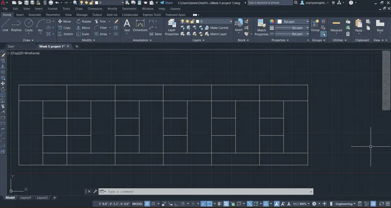
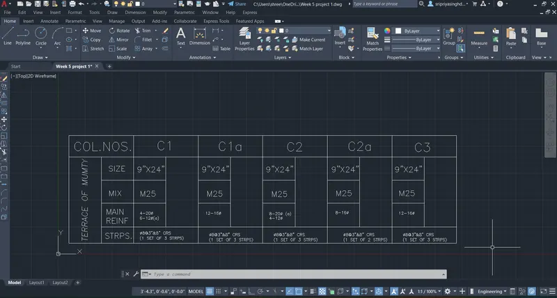
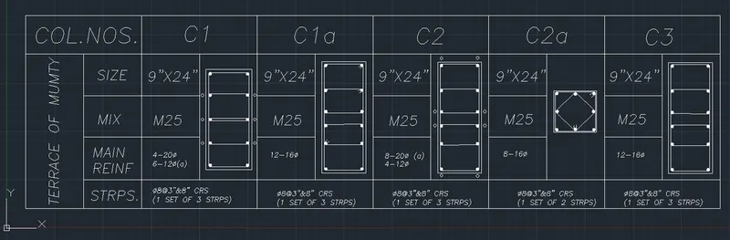
1. Create a column schedule as shown in the figure.
Note: Create a column schedule with the help of lines. Also, insert text with the help of Dtext command or Single Line text.
Hint: Use font name: romans.shx; Height: 8”, Justify: Left
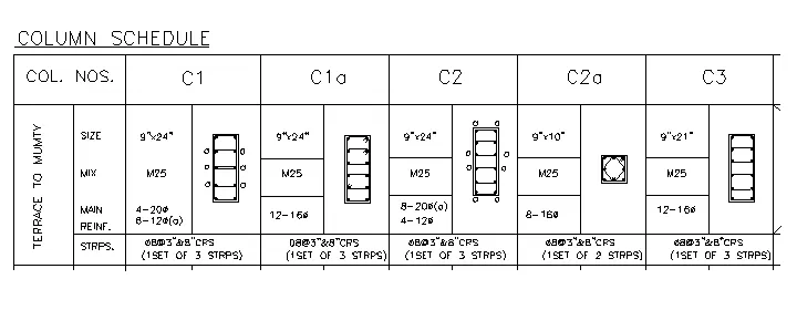
AIM : TO CREATE A COLUMN SCHEDULE AS SHOWN IN THE FIGURE
INTRODUCTION : Create a column schedule with the help of lines and inserting text.
PROCEDURE :
STEP-1
- Open AutoCAD 2022
- open a new drawing
- enter the value of startup as 1
- create a new dilog box
- select advance setup and set the unit as ENGINEERING and precision as 0.00
- then NEXT set the Angle as DESIMAL DEGREE and precision as 0
- then NEXT set the Angle measure EAST
- then next set the Angle direction as Counter clock wise
- then NEXT set the area as width 1' and length 9"
- then set the limit by command LIM in the command box as lower left corner 0,0 and upper right corner 100,100
- then press enter
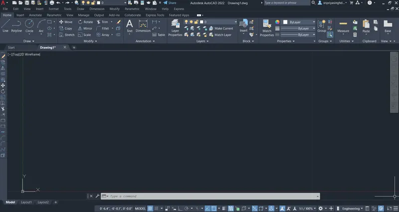
- Choose line command from tool panel
- Specify the first point as 1,1
- Specify the second point as 1,11
- Specify the third point as 36,11
- Specify the forth point as 36,1
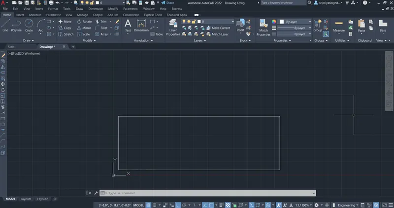
- then close
- then offset the left corner line as 6" and repeat it 4 times
- offset the upper line by 2"
- offset the lower line by 1.5"
- offset the left line as 3" and repet it
- then trim the unwanted lines
- then offset the upper line as per requirement
- then trim the unwanted lines
STEP-2
- Command ST for STYLE TEXT
- Select the fond style as romans.shx
- set the text height 8"
- then apply and close
- type all the speciman that given in the above figure
- then change the text size as 5" and type all small harecters in the table given in the figure
- Then for first row angle text will be their for that we have to give command DT press enter
- then specify the first point of text and angle of text
- then press enter and
- write the sentence
STEP-3
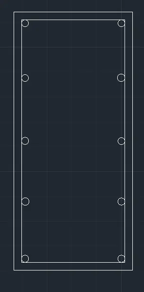
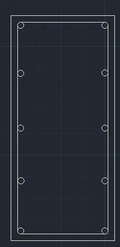
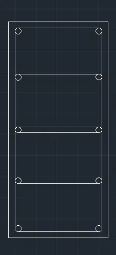
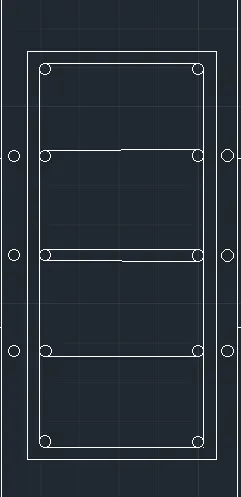
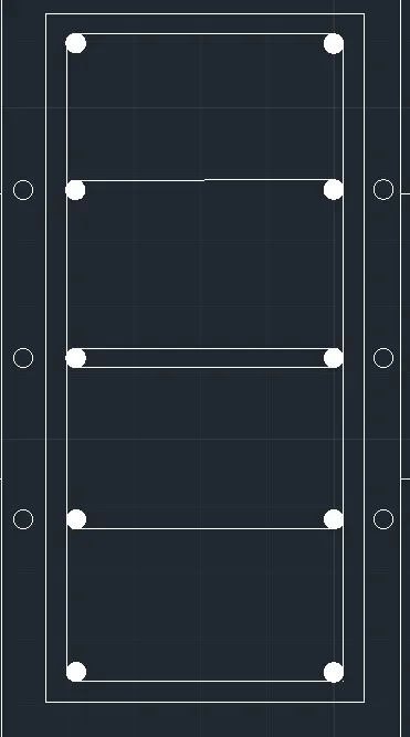
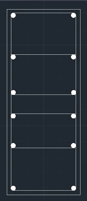
- insert a rectangle on c1 row empty space as specifiedd in the given figure
- then insert circle as per requirement
- then hatch the circle and set as solidd hatch
- and repeat the same procecess for C1a, C2, C2a, C3 as per specified
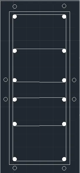
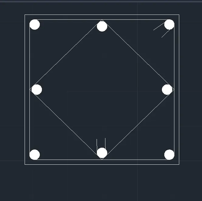
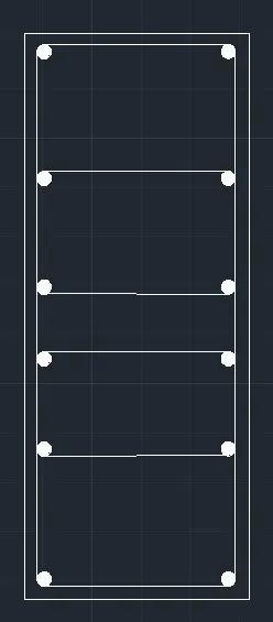
RESULT:
2. Create a window schedule as shown in the figures:
Window Schedule:
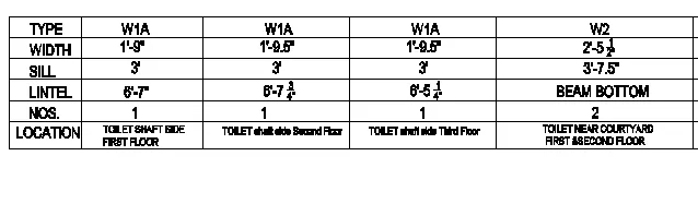
AIM : TO CREATE A WINDOW SCHEDULE AS SHOWN IN THE FIGURE
INTRODUCTION : The window schedule is created by by the help oftable tool. and specifications are written by the given figure
PROCEDURE :
STEP- 1
- Open AutoCAD 2022
- open a new drawing
- enter the value of startup as 1
- create a new dilog box
- select advance setup and set the unit as ENGINEERING and precision as 0.00
- then NEXT set the Angle as DESIMAL DEGREE and precision as 0
- then NEXT set the Angle measure EAST
- then next set the Angle direction as Counter clock wise
- then NEXT set the area as width 1' and length 9"
- then set the limit by command LIM in the command box as lower left corner 0,0 and upper right corner 100,100
- then press enter
STEP-2
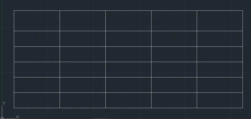
- Home - ribbon - annotation - table
- put the value in column 5
- and row 4
- set first row cell style as data
- set second row cell style as data
- click ok and set the table in proper position
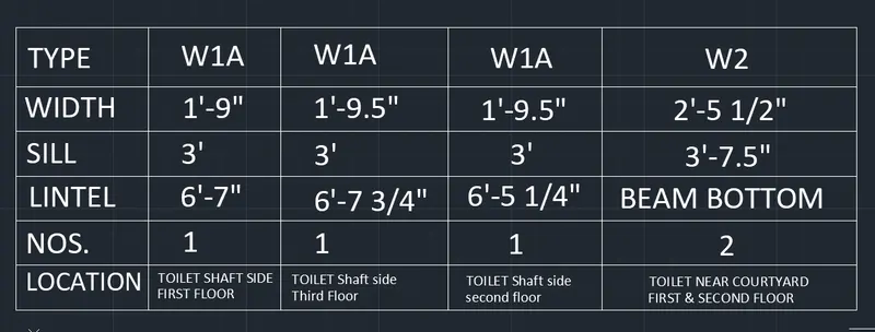
THEN WRITE THE SPECIFICATION GIVEN IN THE FIGURE
RESULT
3. Create the drawing template as shown in the figure:< Use the Notes as in the figure>
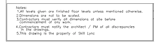

AIM : TO CREATE THE DRAWING TAMPLATE AS SHOWN IN THE FIGURE
INTRODUCTION: The drawing tamplete is created by using line, offset and trim command
PROCEDURE :
STEP- 1
- Open AutoCAD 2022
- open a new drawing
- enter the value of startup as 1
- create a new dilog box
- select advance setup and set the unit as ENGINEERING and precision as 0.00
- then NEXT set the Angle as DESIMAL DEGREE and precision as 0
- then NEXT set the Angle measure EAST
- then next set the Angle direction as Counter clock wise
- then NEXT set the area as width 1' and length 9"
- then set the limit by command LIM in the command box as lower left corner 0,0 and upper right corner 100,100
- then press enter
STEP-2
- Create the above given table by useing line tool
- as specified as in the given figure
- then offset as per requirement
- and trim the external part

then write the specification given in the above figure
RESULT

4. Create the list of drawing schedule as shown in the figure:
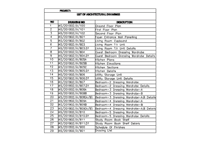
AIM: TO CREATE DRAWING SCHEDULE AS SHOWN IN THE FIGURE
INTRODUCTION: CREATE THE ABOVE SCHEDULE BY USING TABLE TOOL
PROCEDURE:
STEP- 1
- Open AutoCAD 2022
- open a new drawing
- enter the value of startup as 1
- create a new dilog box
- select advance setup and set the unit as ENGINEERING and precision as 0.00
- then NEXT set the Angle as DESIMAL DEGREE and precision as 0
- then NEXT set the Angle measure EAST
- then next set the Angle direction as Counter clock wise
- then NEXT set the area as width 1' and length 9"
- then set the limit by command LIM in the command box as lower left corner 0,0 and upper right corner 100,100
- then press enter
STEP-2
- Home - ribbon - annotation - table
- put the value in column 3
- and row 32
- set first row cell style as tital
- set second row cell style as tital
- click ok and set the table in proper position

then write the specification given in the above drawing
RESULT
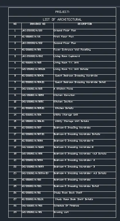
5. Create the Beam detail as shown in the figure and provide text wherever given.
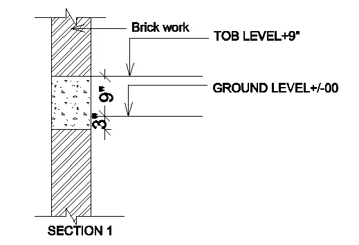
AIM: CREATE THE BEAM DETAIL AS SHOWN IN THE FIGURE
INTRODUCTION: THE BEAM WILL BE CREATED BY THE HELP OF LINE AND HATCHING TOOL.
PROCEDURE:
STEP- 1
- Open AutoCAD 2022
- open a new drawing
- enter the value of startup as 1
- create a new dilog box
- select advance setup and set the unit as ENGINEERING and precision as 0.00
- then NEXT set the Angle as DESIMAL DEGREE and precision as 0
- then NEXT set the Angle measure EAST
- then next set the Angle direction as Counter clock wise
- then NEXT set the area as width 1' and length 9"
- then set the limit by command LIM in the command box as lower left corner 0,0 and upper right corner 100,100
- then press enter
STEP-2
- Choose the line command
- specify the first point as 1,1
- specify the second point as @9",0
- specify third point as @0,4'
- specify the forth point as @-9",0
- then close
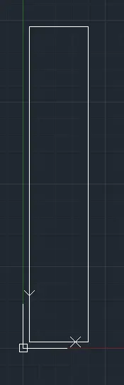
- then offset the top horizontal line at the distance of 1' twice towards down
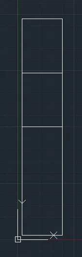
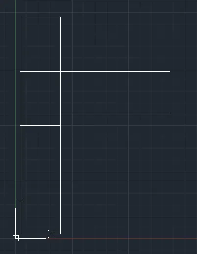
- then stretch the first offset line at the distance of 2' from right side
- then offfset the stretched line for 9" towards down
- then trim the unwanted line
- then hatch the figure according to given drawing
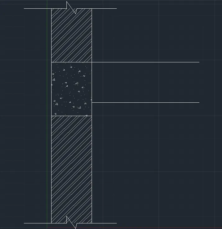
- then write the dimension and lebeling of the given figure
RESULT