Creating a Residence Layout, Seating plan, Toilet and Utility room plan using AutoCad
Creating a Residence Layout, Seating plan, Toilet and Utility room plan using AutoCad
Aim of the project:
1. Residence Plan:
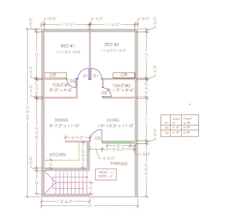
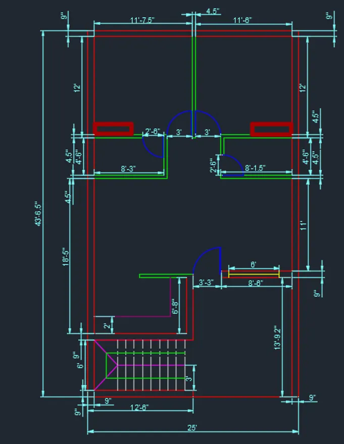
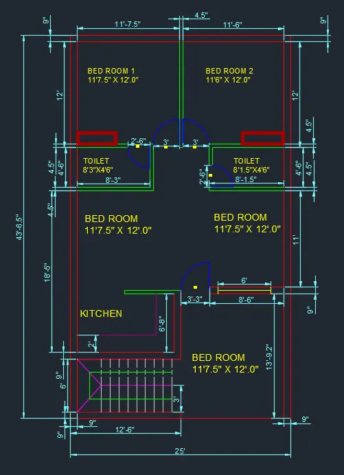
Sketch the layout of a residence as shown in the Figure 1. Consider all dimensions as reference to sketch the unit plan. Also the text in the layout are only for reference. Assume the missing dimensions. Also, refer the schedule for size of the doors.
INTRODUCTION :
To Sketch the layout of a residence as shown in the above picture. Consider all dimensions as reference to sketch the unit plan. Also the text in the layout are only for reference. & Assume the missing dimensions. Also, refer the schedule for size of the doors.
Procedure :
STEP-1
- Go to start menu select AutoCAD 2022
- In the command section type STARTUP and press Enter
- Enter the startup value as 1
- Go to application menu and open a new file
- In the New Drawing open the dilog box and do the advanced setup and select the Unit of measurement as Engineering and select precision as 0-0.00
- set the limits by entering limits command in command section as the lower left corner is specified as 0'0.0",0'0.0", and upper right corner is specified as 100',100'.
- Set the units command in the command section
- in the units dilog box select Engineering in type 0'-0.0" in precision and select inches in insertion scale.
- and click OK
STEP-2
- Click on layer properties in the layer panel on ribbon
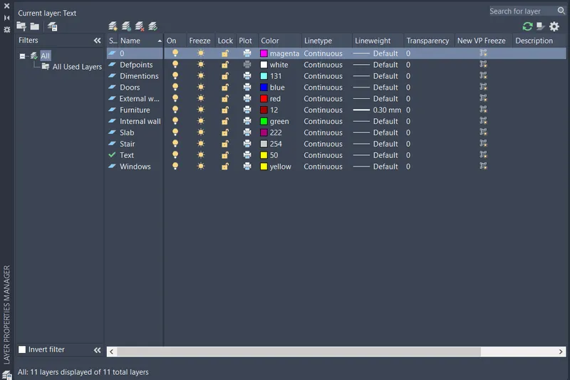
- Click on new layers - External wall, Internal wall, doors, windows, cubboard, stairs, slab, dimension, text
- Specify different colour to diffirient layers then close the layer properties dilog box
STEP-3
- For starting the drawing, select the External wall as the defult layer in the layer panel
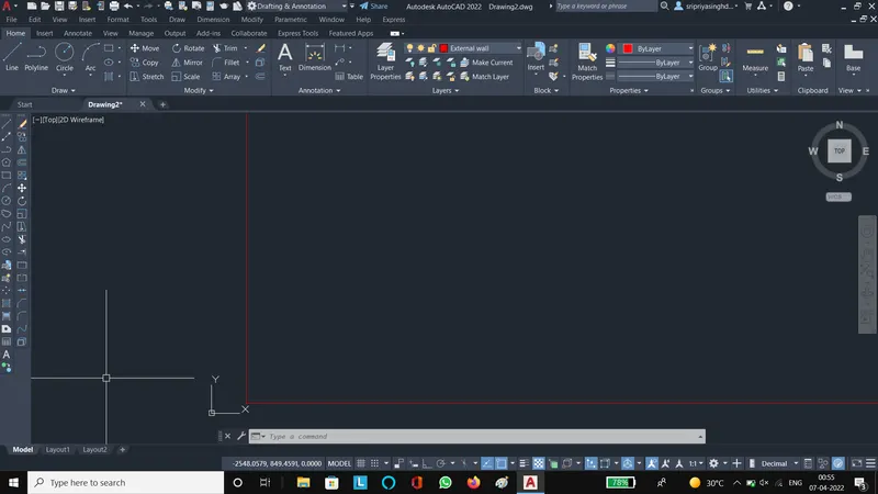
- select the command section and type XLINE command and enter it
- Draw one vertical and horizontal line , intersecting at a point
- Then press Esc to cancel the recent command
- Then select the trim tool and select edge option and click No extend and trim the extructed lines
- Then press Esc to cancel the recent command
STEP-4
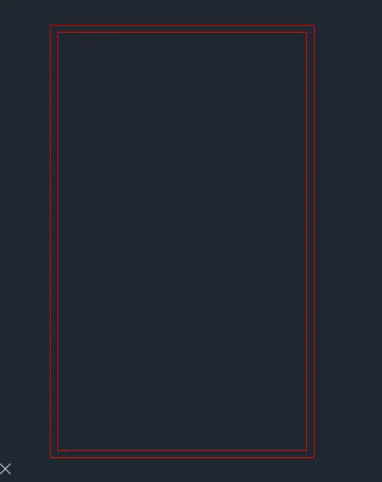
- Select the offset tool
- And offset the both horinzontal and vertical line at 9" on the desired side
- Then vertical outer line is offseted at a distance of 25' , whih is then offseted to a distance of 9" as is the thickness of the wall
- The horizontal outer line is offseted to a distance of 43'6.5", which is then offsetted to a distance of 9" as is the thickness of the wall
- Then Press Esc to cancel the recent command
- Then trim the unwanted line by trim command
STEP-5
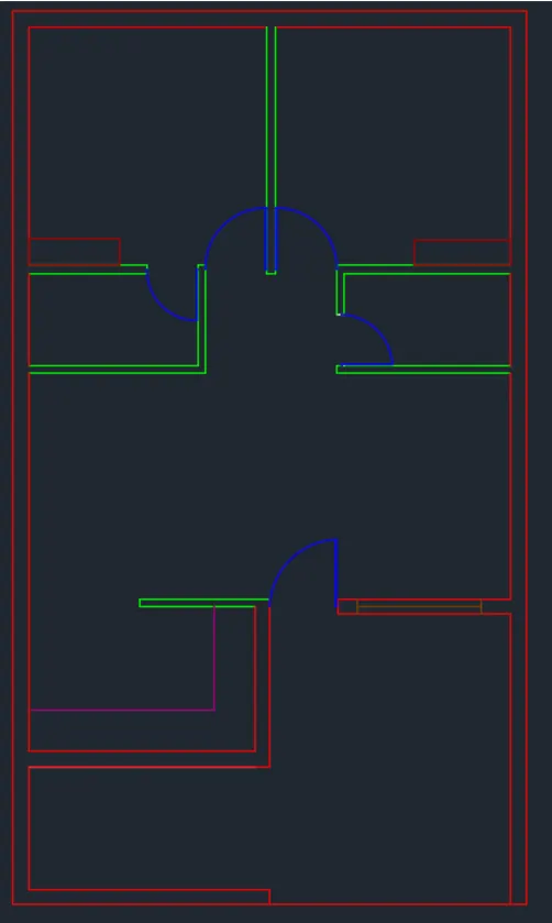
- Then repeat the offset command to create all External wall according to the dimensions given in plan
- Then offset the bottom inner horizontal line is at distance of 6' and the line is again offsetted at distance of 9" as is the thickness of the external wall
- Then offset the bottom outer horizontal line is at distance of 13'9.5", and the line is again offsetted at distance of 9" as is the thickness of the external wall
- Then offset the left outer vertical line at distance of 12'6", and the line is again offseted at a distance of 9" as is thickness of the exterrnal wall.
- Then the external wall are trimmed, erased, extended and joined to edit the drawing
- when all the external wall are created then select the internal wall layer from layer property panel
- Select the offset command
- Specify the offset distance, select the line to offset and click on the direction we need for the line
- offset the internal wallls at 4.5"
- the press Esc to cancel recent command
- then trim, erase, extend fillet or join the drawing as per requirement
Step-6
- To Draw the Door, select the door layer as the default layer in the layeer panel
- Select line tool
- Draw door as specified position
- Door D3 is created at the enterance at the width of 3'3"
- Press Esc
- Selecct arc tool from the ribbon choosr start,end,direction oprion then draw the arc in according to the door specification
- Select the line tool
- Door D1 is created at the entrance of bed room with a width of 3' as given
- Press esc
- Then select Arc tool and from ribbon select start,end,direction option then draw the arc accoring to the D1 door
- select the line tool
- Door D2 is created at the entrance of both 2 bathroom with a width of 2'6"
- Press Esc
- Select the Arc tool from ribbon choose the Start, End, Direction option the draw arc according to the doos
STEP-7
- To draw the kitchen slab, select the kitchen slab layer as defult layer of the layer panel
- Select the offset tool
- Specify the offset distance as 2'
- Offset the vertical and horizontal inner line of the kitchen wall
- Specify the inner point on the side to offset
- Press Esc
- Select the trim tool
- Select Edge click on No extend
- Trim unwanted lines
- Press Esc
STEP-8
- To draw the window select the window layer as the default layer in the layer panel
- Select the line tool
- Draw a line of 9" at the inner edge of te bottom inner wall
- Press Esc
- Select Offset Tool
- Specify the offset distance as 1'3"
- Select the vertical line of 9"length
- Specify the side of offset
- Press Esc
- Select line tool
- join midpoint of the window for creating window
- Press Esc
STEP-9
- To draw the cupboard select the cupboard layer as the default layer in the layer panel
- Select Rectangle tool
- Specify the 1st corner and specify the another corner as per own choice
- then copy the cupboard and drag the copy at another specified point of the cupboard
- Press Esc
Step- 10
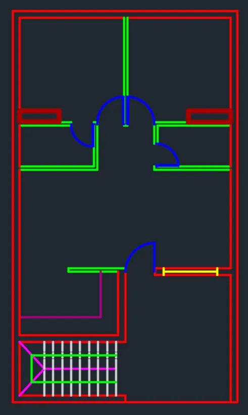
- For stair case drawing, select the stair layer as the defult layer of the layer panel
- Select the line tool
- Draw a line of length 6' at a distance of 2'9" from the bottom left inner corner of the plan
- Press Esc
- Select the offset tool
- Specify the offset distance of 1' then click on desired side and repeate it 8times more for the stairs
- Press Esc
- Select line tool
- Draw a line thrrough the mid point of 6' long line created to divied the stairs
- Press Esc
- Select the trim tool and trim the unwanted lines
- Press Esc
STEP-11
- Select the Dimension layer as the defult layer in the layer panel
- Select the dimention tool
- Click the modify option change the colour of dimension and extension line
- In the symbol and arrow option change the arrow size as 1'
- In the text option change the text height of 1'
- then set is as the curret and close
- Select the dimension tool
- Select the object and drag the dimension line to it's desired location
- And so on
STEP-12
- Then enter text command in the command line
- Specify the start point of text
- Specify the height of the text as 1'
- Copy the text box and place it ehenever it necessary and then type the data on it
- Press Esc
- And Save the drawing
Aim of the project:
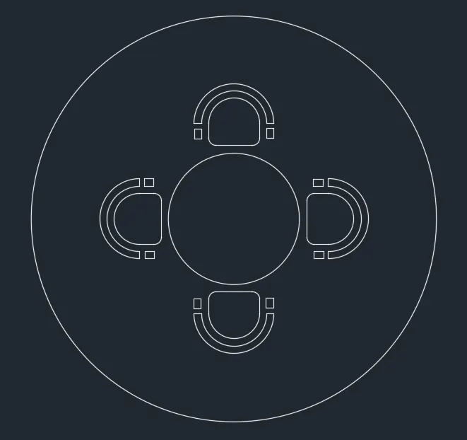
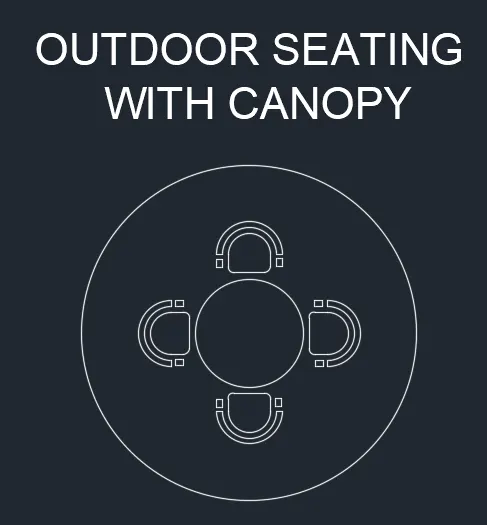
2.Outdoor seating with canopy
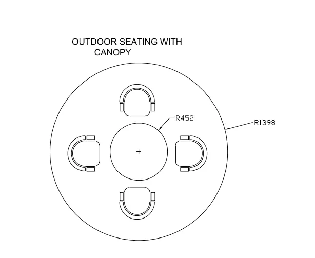
Sketch the seating plan for an outdoor canopy. Assume the dimensions for the seating. Also, consider the dimensions in mm.
INTRODUCTION:
To creating the above plan in AutoCAD using primarily the line, circle, and arc tools.
Procedure:
STEP-1
- Go to start menu select AutoCAD 2022
- In the command section type STARTUP and press Enter
- Enter the startup value as 1
- Go to application menu and open a new file
- In the New Drawing open the dilog box and do the advanced setup and select the Unit of measurement as Engineering and select precision as 0-0.00
- set the limits by entering limits command in command section as the lower left corner is specified as 0'0.0",0'0.0", and upper right corner is specified as 100',100'.
- Set the units command in the command section
- in the units dilog box select Engineering in type 0'-0.0" in precision and select inches in insertion scale.
- and click OK
STEP-2
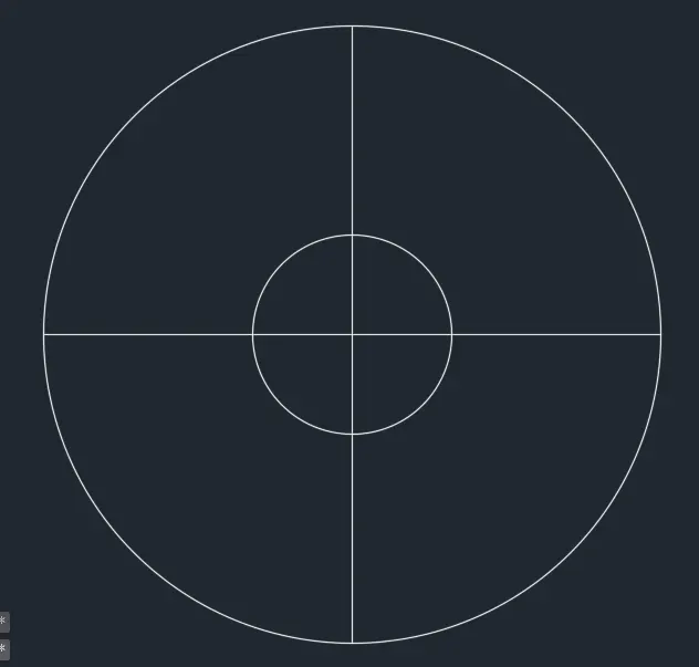
- Click on circle tool in the ribbon
- Select the center, radius option from the drop down list
- Specify the center point of circle as 0,0 in the command line
- Specify the radius as 452
- Again creat a circle useing circle tool
- and select the center, radius option from drop down list
- Specify the center point as 0,0
- and specify the radius of circle as 1398
- Select the line tool
- Draw a horizontal line and a vertical line which divide the circles into 90 degree
- Press Esc
STEP-3
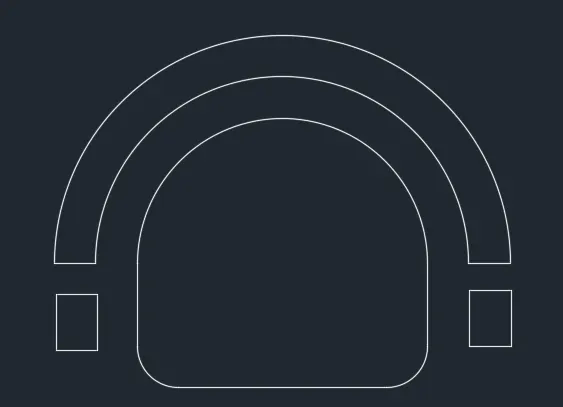
- For draw the chair select the rectangle tool
- Specify the 1st point of the rectangle
- Select the dimension option
- Specify the length of the rectangle as 350 in the command line
- and width as 150
- Move the croser towards upward and enter
- Select the fillet tool from panel
- Select the redius option in the command line, and specify a redius of 50
- Then fillet the 2 bottom corners of the rectangle
- Click on Arc tool and select start, end, angle option from drop down list
- Draw the arc by specifying the start and end point of the arc and specify the angle of arc as 90 degree
- Select the offset tool
- Specify the offset distance as 50
- Select the arc and offset it by the outer side of the arc by twice to creat the handle of the chair
- Press Esc
- Select the line tool and draw lines to close the ends of the chair
- For chair arms we have to select the rectangle tool yyo draw rectangel length 20 and width 50 at the location of the arm hand
STEP-4
- Select the chair and move it to it's proper location outer side of the circle of redius 452
- Select the cair and copy and place it ass per it's position
STEP-5
- Click Text in the command panel
- type what to write in the text
- Press Esc
Aim of the project
3. Part plan for the toilets and utilities room:
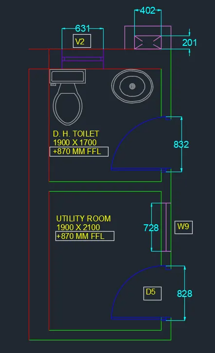
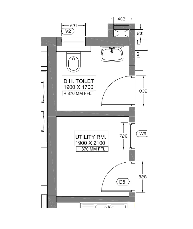
Sketch the part plan for the toilers and utilities room. Consider the outer wall thickness as 300mm and inner wall thickness as 150mm. Also, assume the missing dimension, Texts, dimensions, and hatches are only for references. Also, symbols for toilets and w/c are also for references.
Introduction:
The above plan is creeated in AutoCAD using Construction line, circle and Arc tools
Step-1
- Go to start menu select AutoCAD 2022 in the command line type startup
- Enter the value of Startup as 1
- Go to application menu select new
- In the new drawing dilog box go to advance setup and select Decimal unit of measurement
- Enter the command Limits and set the lower left corner as 0,0 and upper right corner as 2000,2000
- Enter units in command tab
- In the unit dilog box select decimal in type and 0 in precision and millimeters in scale
- Then click ok
STEP-2
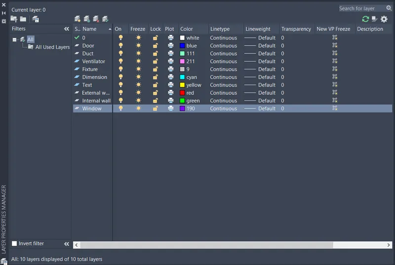
- Click on Layer properties in the layer panel on the ribbon
- Click on new layer to create the following layers - External wall, internal wall, window, door, ventilation, duct, fixtures, dimension and text
- Set diffirient colour inthe diffrient layers
STEP-3
- To begin drawing, select the external wall layer in the layer panel
- Exter XLINE command in the line command tab
- Draw a horizontal line and a vertical line and both are intersecting each other at a point
- Press Esc
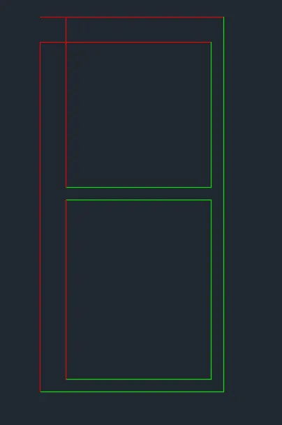
- Select the offset tool
- And offset the external wall at 300
- Select the both line of the draeing
- Next offset the inner horizontal side of the object at a distance of 4250
- Offset the line again at a distance of 300
- Press Esc
- Select the trim tool
- and trim the unwanted lines
- Press Esc
STEP-4
- Select the internal wall layer as the default layer in the layer panel
- Select the command tab enter the command XLINE
- Draw 2 lines horizontal and vertical
- Press Esc
- Select the offset tool
- And offset the internal wall at 150
- offset the inner horizontal line at a distance og 2100
- then offset that line to 150
- Offset the vertical line at a distance of 2100
- the offset that line to 150
- Press Esc
- Select the Trim tool
- Trim the unwanted lines
- Press Esc
STEP-5
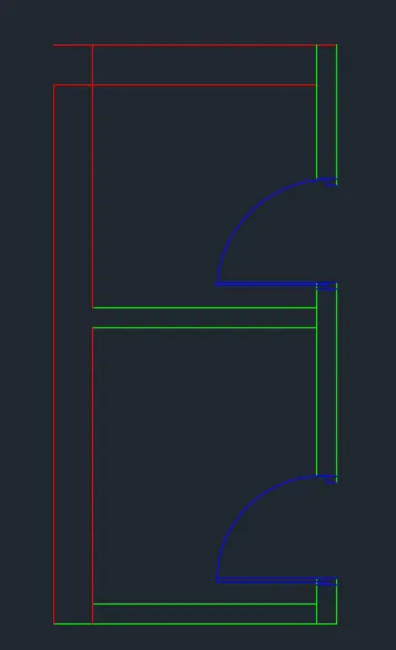
- To draw doors select the door as a default layer in the layer panel
- select the line tool
- Draw door at their given position
- Door D5 is located at utility room and width of the door is 828
- Press Esc
- Select the Arc tool and choose start, end ,direction option then use the arc to make the door
- Select the line tool
- Draw the another door located at the toilet room and width of the door is 832
- Press Esc
- Select the Arc tool and choose start, end ,direction option then use the arc to make the door
STEP-6
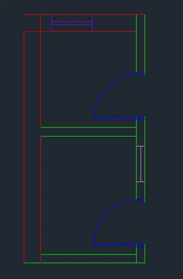
- To draw the window select the window layer as the default layer in the layer panel
- Select the line tool
- Select the position of window in the utility room
- Press Esc
- Select the offset tool
- Offset the distance of the window as 728
- Press Esc
- Select the line tool
- Draw a line joining the mid point of the window line
- Press Esc
- Now draw the ventilator
- select the vantilator layer as default layer of the layer panel
- Select the line tool
- Specify the position of the vantilator in the toilet
- Press Esc
- Select offset tool
- Specify the distance of offset as 631
- Spicify the offset side
- Press Esc
- Select the line tool
- Draw line joining the last two lines to from the section of vantilator
- Press Esc
STEP-7
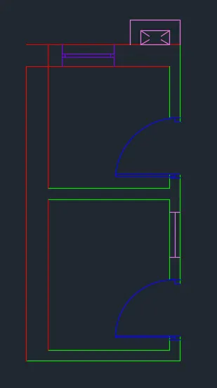
- To draw the duct select the duct layer as the default layer of the layer panel
- Select the rectangle tool
- Specify the 1st point as the top right outer corner of the toilet room
- Select dimension and specify the length of the rectangle as 402 in the commandline
- And width as 201 in the command line
- Move the crosser towards left side of the toilet and press enter
- Then select offset tool
- Specify the offset distance as 150
- Select the rectangle and offset ot by the outer side
- Press Esc
STEP-8
- For the fixtures select the fixture layer as the default layer in the layer panel
- Click on view tab
- From the palettes panel select the toilet and wash basin blocks
- Specify the basse point and position the fixtures according to give drawing
- Enter the dimension command in the command tab to open dimension style manager dilog box
- Click on the modify tab
- under the line option change the colour of the dimension and extension lines
- under the symbol and arrows option change the arrow size to 100
- under the text option change the text height to 100
- Click ok and set as current and close the dilog box
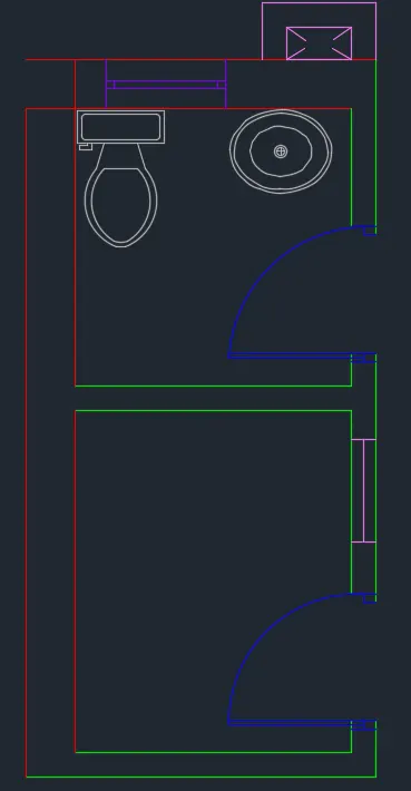
STEP-9
- Select the dimension tool by entering DIM in the command line
- Select the first point and second point of the object to be measured, then drag the dimension line to the desired location, repeat all the object to be measured
- Press Esc
- Enter text command
- Specify the start point of text as required
- Specify height of text as 100
- Specify angle of rotation of text ass 0
- copy the text box to whenever want and the enter the data
- Press Esc