Creation of Column Schedule and Drawing Template using AutoCad
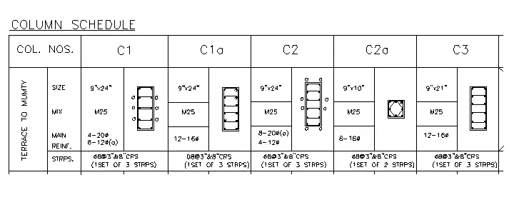
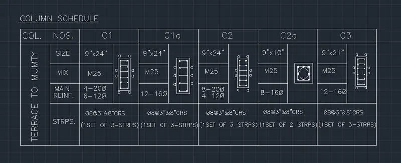
1. Create a column schedule as shown in the figure.
Note: Create a column schedule with the help of lines. Also, insert text with the help of Dtext command or Single Line text.
Hint: Use font name: romans.shx; Height: 8”, Justify: Left
AIM:
To create a column schedule as shown in figure by using AutoCAD.
INTRODUCTION:
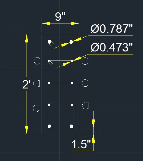
- Column C1 is provided with 4 bars of 20mm dia and 6 bars of 12mm dia. The 12mm dia bars are marked with'a'.
- Column C1a and C3 are provided with 12 bars of 16mm dia bars.
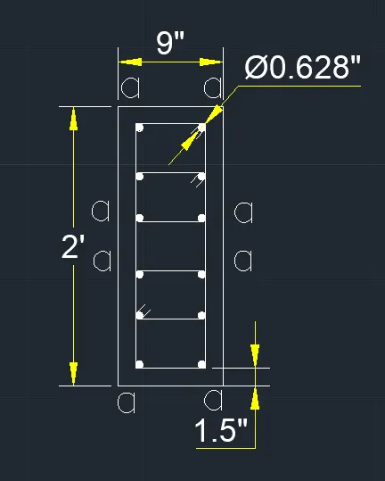
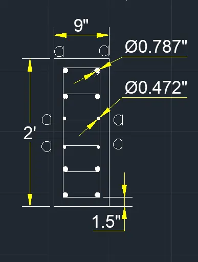
- Column C2 is provided with 8 bars of 20mm dia and 4 bars of 12mm dia. The 20mm dia bars are marked with'a'.
- Column C2a is provided with 8 bars of 16mm dia.
- All columns are provided with 8mm dia stirrups with 3" spacing c/c mear the ends and 8" c/c in mid length.
- The clear cover for all the columns is assumed to be 1.5" (appox 40mm). As per IS 456, the minimum cover to the column should not be less then 40mm.
PROCEDURE:
- Open a new AutoCAD file in imperial units.
- Convert the diameter of the bars into inches. The following table contains conversion (divide by 25.4).
| VALUES IN MM | VALUES IN INCHES |
| 20 | 0.7874 |
| 16 | 0.6299 |
| 12 | 0.4725 |
| 8 | 0.3150 |
- Get in to a new drawing file and set start up settings in to Imprerical
- Set limits as 10',10' by using LI command
- Set the text height as 8" and text style as Romans.SHX by using ST command
- Set th units in architecture.
STEP1:
- Type rectangle in Command prompt : REC; To create C1
- Specify other corner point or [Area/Dimensions/Rotation]:d
- Specify length for rectangles : 9"
- Specify width for rectangles : 24"
- Command: OFFSET
- Specify offset distance : 0.4"
- Select the rectangle and in side of the rectangle
- Create a circle by using circle command and select TTR option
- Select the lines of first corner as tangents and type radius as :0.39" as (10mm radius)
- Mirror the circle at opposite & vertically downwards direction with refrance the mid line of inner rectangle
- Specify the circle of radius 0.23" at a 3 points of 6" equal distance
- Mirror the circle at opposite & vertically downwards direction with refrance the mid line of inner rectangle
- Extensions of circle can be provided by line command.
- Type explode command to explode inner rectangle and copy the line at qadrents with copy command of the circle per figure given
- By trim command trim the extension lines or by using fillet command by radius of the circle.
STEP2:
- Type rectangle in Command prompt : REC; To Create C1a
- Specify other corner point or [Area/Dimensions/Rotation]:d
- Specify length for rectangles : 9"
- Specify width for rectangles : 24"
- Command: OFFSET
- Specify offset distance : 0.4"
- Select the rectangle and in side of the rectangle
- Create a circle by using circle command and select TTR option
- Select the lines of first corner as tangents and type radius as :0.39" as (10mm radius)
- Mirror the circle at opposite & vertically downwards direction with refrance the mid line of inner rectangle
- Specify the circle of radius 0.23" at a 3 points of 6" equal distance
- Mirror the circle at opposite & vertically downwards direction with refrance the mid line of inner rectangle
- Extensions of circle can be provided by line command
- Type explode command to explode inner rectangle and copy the line at qadrents with copy command of the circle per figure given
- By trim command trim the extension lines or by using fillet command by radius of the circle.
STEP3:
- Type rectangle in Command prompt : REC; To create C2
- Specify other corner point or [Area/Dimensions/Rotation]:d
- Specify length for rectangles : 9"
- Specify width for rectangles : 24"
- Command: OFFSET
- Specify offset distance : 0.4"
- Select the rectangle and in side of the rectangle
- Explode the inner rectangle
- Divide in to 5 parts of the inner vertical line and copy the base line of inner rectangle at 5 parts of rectangle
- Draw the circle with TTR method of 0.39" at the corners of the inner rectangle
- and 0.23" at the remaining corners
- Use trim command for removing extra lines.
STEP4:
- Type rectangle in Command prompt : REC; To Create C2a
- Specify other corner point or [Area/Dimensions/Rotation]:d
- Specify length for rectangles : 9"
- Specify width for rectangles : 10"
- Command: OFFSET
- Specify offset distance : 0.4"
- Select the rectangle and in side of the rectangle
- Draw a line joining to all mid point of offset rectangle
- Using circle command with radius 0.314" make a circle by TTR option for all corners at rectangle and rhombus
- Use trim command for removing extra lines.
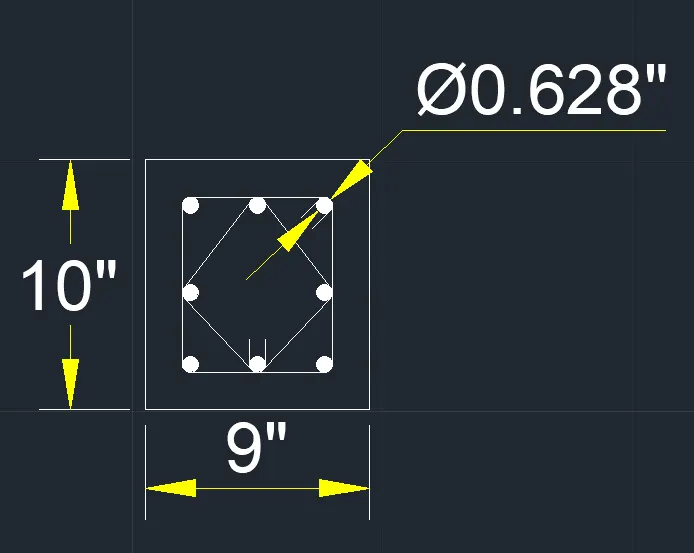
STEP5:
- Type ‘rec’ or rectangle in the command prompt; To create C3
- Specify other corner point or [ Area: Dimension: Rotation]: d
- Specify length for rectangle: Type 9” and press enter
- Specify width for rectangle: Type 21” and press enter
- Offset the rectangle at 0.4"
- Expolde the inner rectangle by explode command.
- Divide in to 5 parts by Divide command
- copy the base line of inner rectangle in to 5 points
- Draw the circle by usiong circle command with TTR option
- Select the corner lines as the tangents and enter radius 0.314".
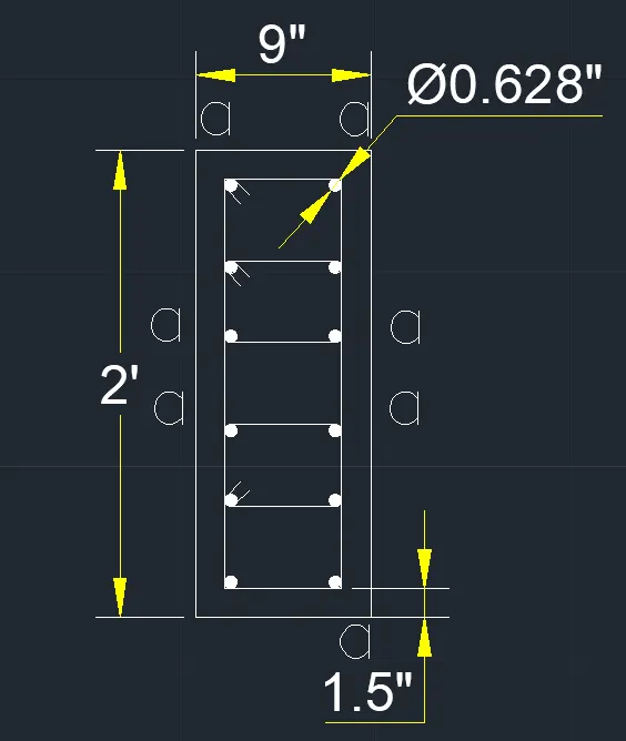
STEP6:
- Create a rectangle as per assumerd size which depends upon sizes of column and text.
- Type rectangle in command prompt > Specify the dimensions
- By using line command and offset command divide the rectangle in to 5 parts X direction and four parts in Y direction.
- To get the clear view of the autocad file change the scale. That is increase the scale by 5". As we know that as we increase the scale, automatically dimension is also increased to avoid such create a new text style by using the command "d" enter.
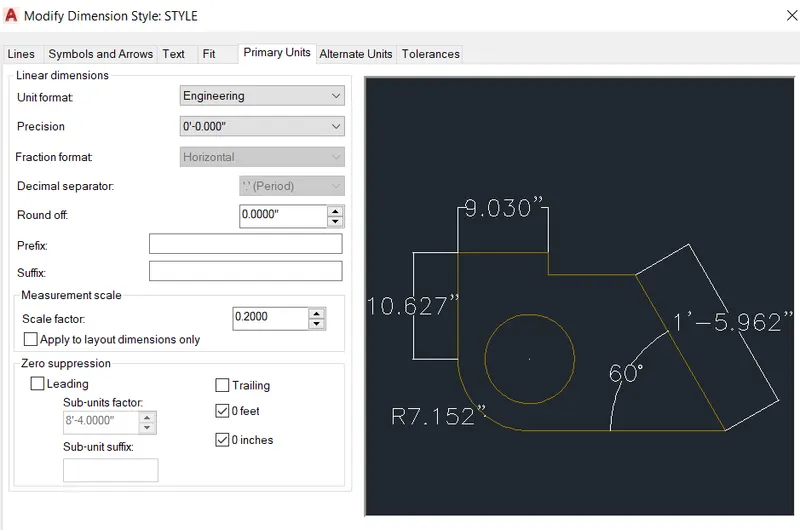
- Change the scale factor to 0.2 to avoid the dimension changes.
- As mentioned change the font name: romans.shx; Height: 8”, Justify: Left
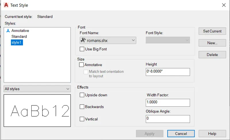
- Thereby create a table in such a way that the drawn autocad files are placed in the table.
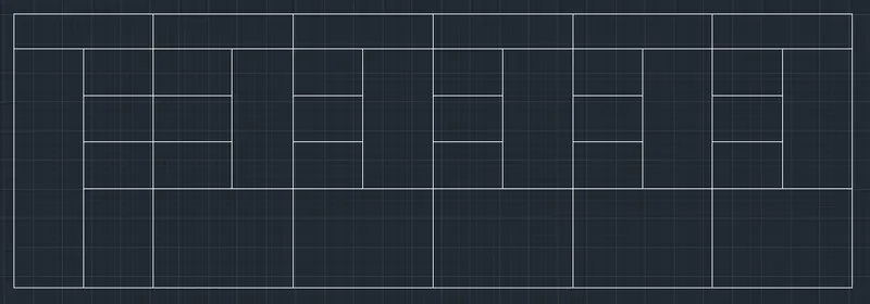
- Using Mtext command, make the text as required.
RESULT:
__________________________________________________________________________________________
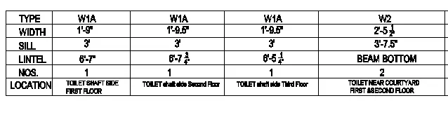
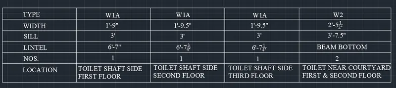
2. Create a window schedule as shown in the figures:
Window Schedule:
AIM:
To create a window schedule as shown in figure.
INTRODUCTION:
The table contains the width, sill and lintel height, their numbers and respective location for different types of beams.
PROCEDURE:
- Open a new AutoCAD file in imperial units.
- Convert the diameter of the bars into inches.
- Type RECTANGLE command in the command box and press enter
- Specify the first point on the screen then second point
- Explode with explode command
- And divide in to six parts from vertical and horizontal direction using divide command.
- set text size 2.5' and texty style in Times New Roman by using ST command.
- Type the text given in schedule by using text command Dtext
- Repeat the above command to fill the text in table.
RESULT:
__________________________________________________________________________________________
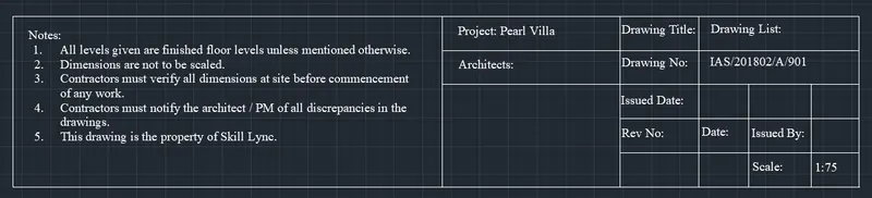
3. Create the drawing template as shown in the figure:< Use the Notes as in the figure>
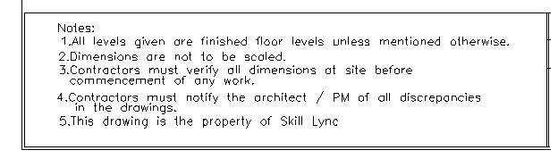

AIM:
To create the drawing template as shown in the figure by using AutoCAD
INTRODUCTION:
To create the table with line command and mtext command.
PROCEDURE:
- Type RECTANGLE command in the command box and press enter
- Specify the first point on the screen then second point
- Explode the rectangle with explode command.
- Type note text with multi text command
- Make cells in rectalgle by using line command
- Type the text given in schedule by using text command DText.
RESULT:
__________________________________________________________________________________________
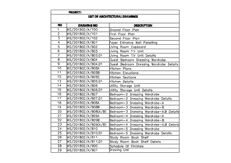
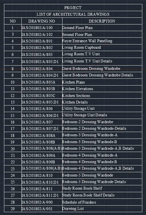
4. Create the list of drawing schedule as shown in the figure:
AIM:
To Create the list of drawing schedule as shown in the figure by using AutoCAD.
INTRODUCTION:
To draw the schedule use the table command and draw the figure in AutoCAD.
PROCEDURE:
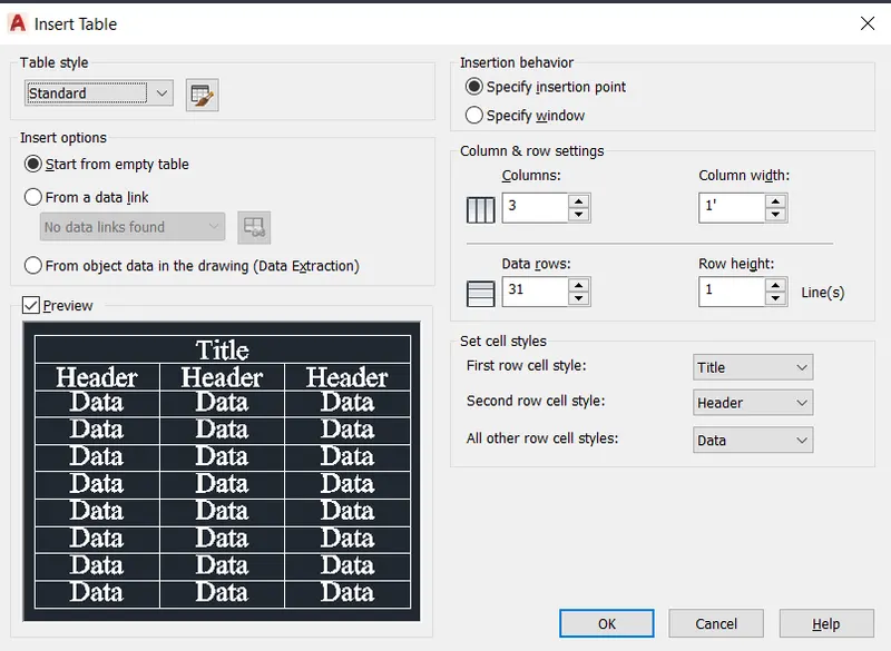
- Open the table command.
- Create a new table style by selecting the required text style, text height, etc. for all the cell styles.
-
Enter the number of rows and columns, set the cell styles and using any insertion behaviour, insert the table.
- Adjust the size of rows and columns.
- Enter the data.
- Make the contents of title and header rows as Bold.
- Give the required justification to the cells and adjust the cell sizes if required.
RESULT:
__________________________________________________________________________________________
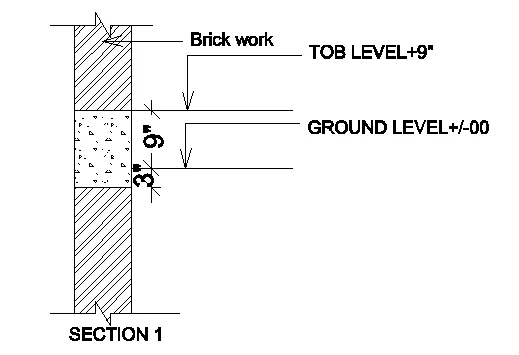
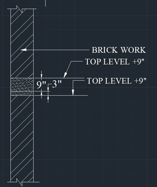
5. Create the Beam detail as shown in the figure and provide text wherever given.
AIM:
To Create the Beam detail as shown in the figure and provide text wherever given by using AutoCAD
INTRODUCTION:
Draw line, offset, hatch and break command to draw the figure in AutoCAD.
PROCEDURE:
- Make two parallel lines 45" long at a distance of 6" from each other.
- Using the breakline command, make a breakline at the top and bottom.
- Make the horizontal lines as shown.
- Give the required labeling using leader and multitext.
- Modify the dimension to match with that in the question. (Arrowheads, suffix ("), etc.)
- Give the hatching of brickwork and concrete as shown.
RESULT:
_________________________________________________________________________________________