Creation of Column Schedule and Drawing Template using AutoCad
create a column schedule as shown figure 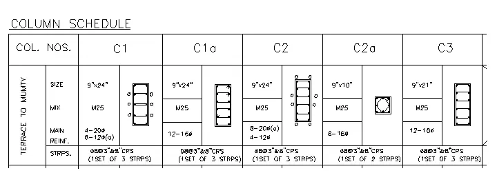
INTRODUCTION
1. COLUMN C1 is provided with 4 bars of 20mm dia.
and 6 bars of 12mm dia.
the 12mm bars dia bars are markede with 'a'.
2. column C1a and column c3 are provided with 12 bars of 16mm dia bars.
3. column C2 is provided with 8 bars of 20mm dia and 4 bars of 12 mm dia and the 20mm dia bars are mareked with 'a'.
4. column is c2a is provided with 8 baars of 16 mm dia.
5. all columns are provided with 3" spaning c/c innmid-length.
6. the colure cover for all the xolumns is assumed to be 1.5" (n approx 40mm.) as per is 256, the minimum cover to the
column sholud not be less than 40mm
PROCEDURE
1. open a new AUTO CAD file in imperial units.
2. convert the diametar of the bars into inches. the following table contains conversion (divide by 25.4)
VALUES IN MM VALUES IN INCHES
20 0.7874
16 0.6299
12 0.4725
8 0.3150
INSTRUCTIONS FOR STEPS 3-7:
A. the dimensions for the bars on the left are same as of the bars on the right.
B. THE logitudinal and stirrups are hatched with a white solid fill.
3. make the column C1 as shonwn.
4. make the column c1a as shown.
5. make the column c2 as shown.
6. make the column c2a as shown.
7. make the column 3 as shown.
8. make the column as shown.
RESULT
COLUMN SCHEDULU
COL. NOS. C1 C1A C2 C2A C3
TTM SIZE 9"X24" 9"X24" 9"X24" 9"24" 9"24"
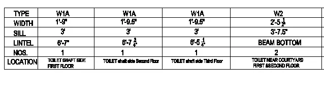
2. CREATE A WINDOW SCHEDULE AS SHOWN AS IN THE FIGURE.
INRODUCTION
THE total contains the width, sill and respective location for the different types of beams.
PROCEDURE
1. MAKE THE FOLLOWING TABEL
2. using multilines, fill in the following data with justification middle center mc
3.using multiline, give the heading "window schedule " and underline it.
RESULT
WINDOW SCHEDULE
TYPE WIA WIA WIA
width 1'9" 1'9.5" 2'5 1/2"
CREATE THE DRAWING TEMPLATE AS SHOWN IN THE FIGURE.

PROCEDURE
1. MAKE THE following table.
2. using multitext, tepe the following as shown and place it in first column.
(height =2.5' and fort = arial=arial)
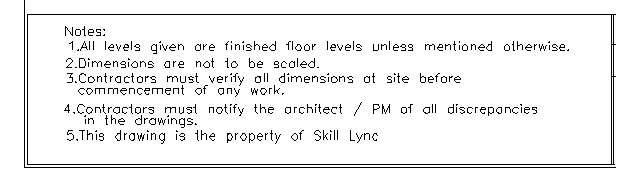
3. type the following in rest of the cells as shown using multitext (make a vertical line after rve.no ) ( text height =2.5" and font = arial)
RESULT
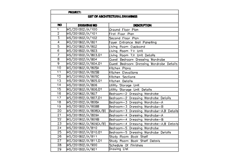
4 CREATE THE LIST OF DRAWING SCHEDULE AS SHOWN IN THE FIGURE
PROCEDURE
1. OPEN THE TABLE COMMAND.
2. create a new table style by selecting the required text style, text heightect. for the cell the cell styles.
3. enter the number of rows and columns, set the cell styles and using any insertion behaviour, insert the table.
4. adjest the size of rows and columns.
5. enter the data.
6. make the contents of title and header rows as bold.
7. give the required jestification to the cells and adjust the cell sizes if required.
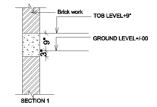
5. CREATE THE BEAM DETAIL AS SHOWN IN THE FIGURE
PROCEDURE
1. make two parallel line 45" long at a distance of 6" from each other.
2. using the breakline command, make a briakline at the top and bottom.
3. make the horizontal lines
4. give the required labeelineng using lender and mulititext.
5. modify the diamensions to mach with that in the reqestin. (arrowheads, surffix ("), etc.)
6. give the hatching of brick and concrete as shown.
RESULT