Creation of Column Schedule and Drawing Template using AutoCad
Challenges – Week 5
- Create a column schedule as shown in the figure.
Note: Create a column schedule with the help of lines. Also, insert text with the help of D text command Or Single Line text.
AIM:
- To determine the column schedule with the help of lines . Also insert text with the help of D text command or Single line text.
INTRODUCTION:
- Structural columns are identified in a column schedule by intersecting grid lines and by their top and bottom constraintys and offsets. They are placed into the column schedules according to these identifications.
PROCEDURE:
- The column schedule are created with the help of lines, Also insert the d text command.
- It should be toolbar – insert the draw line command and draw it .
- And the strips details are make at auto cad and then insert the picture of strips .
- The column schedule is a schedule which the details of column will be collected in the construction for design purpose. The column scheduling is very important thing in column detalling.
- To create the schedule , open the schedules menu on the view tab and select the graphical column schedule tool. After the schedule is generated ,you can modify its attributes in the properties palette.
- Table graphics are automatically generated to fit the structural model column layout, and are defined in the graphical column schedule settings. The imported structural model grid and story elevation information is used to generate grid graphics and dimensions.
|
Col. |
nos |
C1 |
C1a |
C2 |
C2a |
C3 |
||||||
|
TERRACE TO MUMTY |
SIZE |
9’’X24’’ |
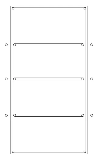 |
9’’x24’’ |
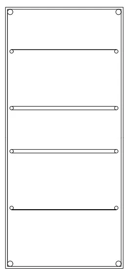 |
9’’x24’’ |
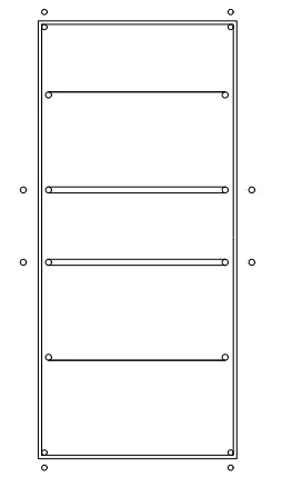 |
9’’x10’’ |
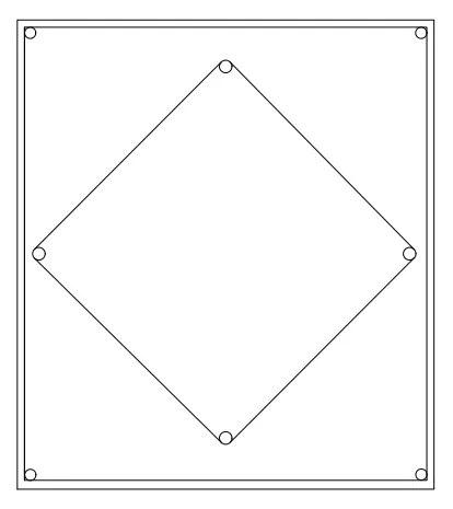 |
9’’x21’’ |
|
|
|
MIX |
M25 |
M25 |
M25 |
M25 |
M25 |
|||||||
|
12-16 dia |
||||||||||||
|
MAIN. RFT |
4-20dia 6-12dia |
12-16dia |
8-16 dia |
|||||||||
|
8-20 dia 4-12dia |
||||||||||||
|
STRPS. |
8@3’’& 8CRS (1 set of 3 strips) |
8@3’’& 8CRS (1 set of 3 strips) |
8@3’’& 8CRS (1 set of 3 strips) |
8@3’’& 8CRS (1 set of 3 strips) |
8@3’’& 8CRS (1 set of 3 strips) |
Result:
- To determined the drawing templates as using MS office.
- Create a window schedule as shown in the figures:
Window Schedule:
AIM:
- To determine the window schedule as using MS word.
INTRODUCTION:
- A window schedule is similar to a door schedule in that it provides an organized presentation of the pertinent window characteristics. Window schedules include quantity, type, model, manufacturer, size, rough opening, materials, glazing and finish.
PROCEDURE:
- Make a column and row from the insert - table .
- It should be on a door schedule as hinges ,locks, latches,handles,push plates, pull handles, kicker plates, vision panels, stops, closers etc…
- The most common window size or average window size is 24 x 36.
- It describes the location of windows , their types vv
|
TYPE |
W1A |
W1A |
W1A |
W1A |
|
WIDTH |
1’9’’ |
1’-9.5’’ |
1’9.5’’ |
2’-51/2’’ |
|
SILL |
3’’ |
3’’ |
3’’ |
3’’-7.5’’ |
|
LINTEL |
6’-7’’ |
6’-7 ¾’’ |
6’-51/4’’ |
Beam bottom |
|
NOS. |
1 |
1 |
1 |
2 |
|
LOCATION |
Toilet Shaft side first floor |
Toilet Shaft side second floor |
Toilet Shaft side third floor |
Toilet near courtyard first & second floor |
Result:
- To determined the drawing templates as using MS office.
- Create the drawing template as shown in the figure: & It; Use the Notes as in the figure & It;
AIM:
- To determine the drawing template as using MS office.
INTRODUCTION:
- A drawing template file is a drawing file that has been saved with a. dwt file extension, and it specifies the styles, settings, and layouts in a drawing, including title blocks. The default drawing template files are provided as samples.
PROCEDURE:
- Templates have pre-dimensional holes that are in the right scale, so engineers can accurately draw a specific symbol or sign. Letter templates can be used to draw text (such as digits and letter characters),while others can be used to draw circles and arcs.
- A template is a form, mold, or pattern used as a guide to making something. Here are some examples: A ruler is a template when used to draw a straight line. A document in which the standard opening and closing parts are already filled in is a template that you can copy and then fill in the variable parts.
|
Notes: 1. All levels given are finished floor levels unless , mentioned otherwise. 2. Dimensions are not to be scaled. 3. Contractors must verify all dimensions at site before commencement of any work. 4. Contractors must notify the architect / PM of all discrepancies in the drawing. 5. This drawing is the property of skill-lync |
|
Notes: 1. All levels given are finished floor levels unless , mentioned otherwise. 2. Dimensions are not to be scaled. 3. Contractors must verify all dimensions at site before commencement of any work. 4. Contractors must notify the architect / PM of all discrepancies in the drawing. This drawing is the property of skill-lync |
PROJECT PEARL VILLA |
Drawing Title: |
Drawing list |
|||
|
ARCHITECTS: |
Drawing no: |
IAS/ 201802/A/901 |
||||
|
Issued date: |
||||||
|
REV NO: |
DATE |
ISSUED BY: |
||||
|
SCALES |
1:75 |
|||||
Result:
- To determined the drawing templates as using MS office.
- Create the list of drawing schedule as shown in the figure:
AIM:
- To determine the drawing schedule as using MS office.
INTRODUCTION:
- A schedule of drawing is an itemized list of drawings required for a building project. It can be included as part of an invitation to tender, or may be prepared as part of a design management plan.
PROCEDURE:
- A schedule of drawings may include all the drawings required for a project, or on longer, more complex projects,it may be specifically prepared for a certain discipline, specialist or for a particular aspect of the works(such as a planning application).
- It may include:
- Project name
- Drawing types and purposes
- Drawing numbers and revisions.
- Drawing titles.
- Drawing originators
- Drawing formats
- Drawing locations.
- Scales
- Original sizes.
- Dates prepared, issued or required.
- Additional notes.
|
PROJECT: |
||
|
LIST OF ARCHITECTURAL DRAWINGS |
||
|
NO |
DRAWING NO |
DESCRIPTIPON |
|
1 |
IAS/201802/A/100 |
GROUND FLOOR PLAN |
|
2 |
IAS/201802/A/101 |
FIRST FLOOR PLAN |
|
3 |
IAS/201802/A/102 |
SECOND FLOOR PLAN |
|
4 |
IAS/201802/A/801 |
FOYER ENTRANCE WALL PANELLING |
|
5 |
IAS/201802/A/802 |
LIVING ROOM CUPBOARD |
|
6 |
IAS/201802/A/803 |
LIVING ROOM T.V UNIT |
|
7 |
IAS/201802/A/803.D1 |
LIVING ROOM T.V UNIT DETAILS |
|
8 |
IAS/201802/A/804 |
GUEST BEDROOM DRESSING WARDROBE |
|
9 |
IAS/201802/A/804.D1 |
GUEST BEDROOM DRESSING WARDROBE DETAILS |
|
10 |
IAS/201802/A/805A |
KITCHEN PLAN |
|
11 |
IAS/201802/A/805B |
KITCHEN ELEVATION |
|
12 |
IAS/201802/A/805C |
KITCHEN SECTIONS |
|
13 |
IAS/201802/A/805.D1 |
KITCHEN DETAILS |
|
14 |
IAS/201802/A/806 |
ULITITY STORAGE ROOM |
|
15 |
IAS/201802/A/806.D1 |
ULITITY STORAGE ROOM DETAILS |
|
16 |
IAS/201802/A/807 |
BEDROOM -2 DRESSING WARDROPE |
|
17 |
IAS/201802/A/807.D1 |
BEDROOM -2 DRESSING WARDROPE |
|
18 |
IAS/201802/A/808A |
BEDROOM -3 DRESSING WARDROPE |
|
19 |
IAS/201802/A/808B |
BEDROOM -3 DRESSING WARDROPE |
|
20 |
IAS/201802/A/808(A/B) |
BEDROOM -3 DRESSING WARDROPE(A/B) DETAILS |
|
21 |
IAS/201802/A/809A |
BEDROOM -4 DRESSING WARDROPE |
|
22 |
IAS/201802/A/809B |
BEDROOM -4 DRESSING WARDROPE |
|
23 |
IAS/201802/A/809(A/B) |
BEDROOM -4 DRESSING WARDROPE (A/b) DETAILS |
|
24 |
IAS/201802/A/ 810 |
BEDROOM -5 DRESSING WARDROPE |
|
25 |
IAS/201802/A/810.D1 |
BEDROOM -5 DRESSING WARDROPE DETAILS |
|
26 |
IAS/201802/A/811 |
STUDY ROOM BOOK SHELF |
|
27 |
IAS/201802/A/811.D1 |
STUDY ROOM BOOK SHELF DETAILS |
|
28 |
IAS/201802/A/900 |
SCHEDULE OF FINISHES |
|
29 |
IAS/201802/A/901 |
DRAWING LIST |
Result:
- To determined the drawing schedule as using the MS office.
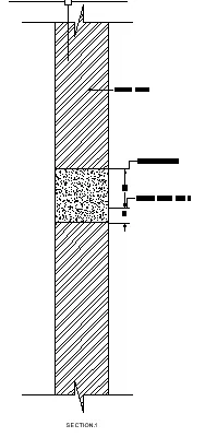
- Create the Beam detail as shown in the figure and provide text wherever given.
AIM:
- To determine the beam detail as using Auto CAD.
INTRODUCTION:
- A beam is a structural element that primarily resists loads applied laterally to the beam’s axis (an element designed to carry primarily axial load would be a strut or column). Its mode of deflection is primarily by bending. The loads applied to the beam result in reaction forces at the beam’s support points.
PROCEDURE:
STARTING AUTO CAD SOFTWARE,
START MENU: Auto CAD
INTERFACE OF AUTO CAD:
- File name
- Panel
- TAB
- START TAB
- Visual style control
- Viewport controls
- Command line
- Status bar
- View cube
- Navigation bar
- Drawing area
Command – Cursorsize (value)
DIMORDINATE Specific co-ordinate (x,y)
- Draw – Rectangle – view cube ( Rotate ) XYZ axis
- Relative co ordinate : choose the line command and specify the first point
- Specify the next point and more point to make the object an auto cad.
- Command : OFFSET for wall thickness =0.23m(9’’)
- Command : TRIM (TR -DOUBLE ENTER) to trim the unneccesary cut lines.
- it make an beam details and mention the dimensions and art of work.
Result:
To determined the beam details using as Auto CAD.