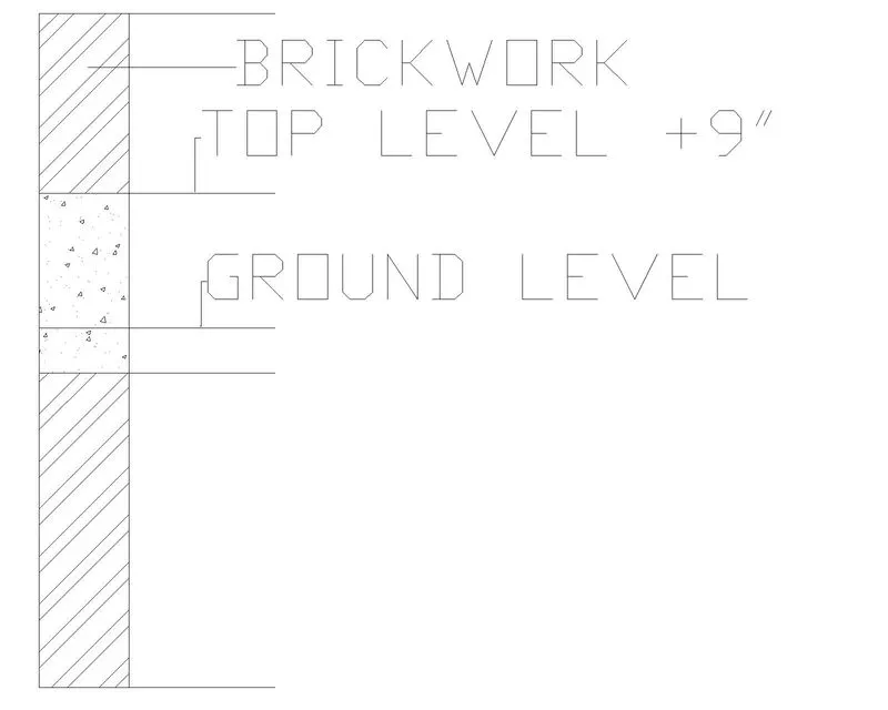
Creation of Column Schedule and Drawing Template using AutoCad
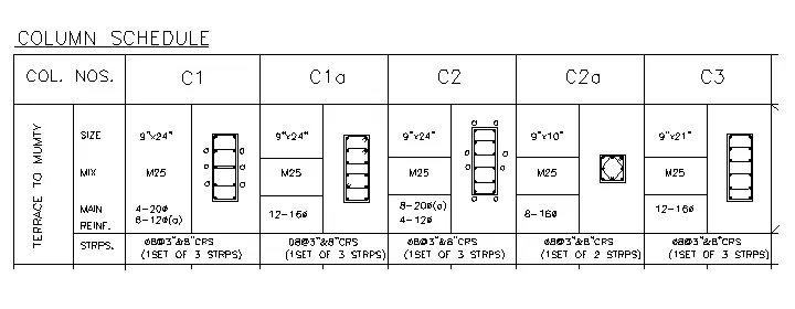
1. Create a column schedule as shown in the figure.
Note: Create a column schedule with the help of lines. Also, insert text with the help of Dtext command or Single Line text.
Hint: Use font name: romans.shx; Height: 8”, Justify: Left
INTRODUCTION
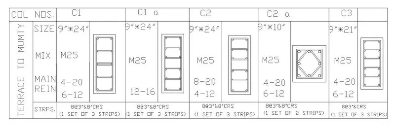
1] Column C1 is povided with 4 bars of 20mm dia. and 6 bars of 12mm dia. The 12mm dia bars are marked with 'a'.
2] Column C1a and column C3 are provided with 12 bars of 16mm dia bars.
3] Column C2 is provided with 8 bars of 20 mm dia and 4 bars of 12 mm dia. the 20 mm dia bars are marked with 'a'.
4] Column C2a is provided with 8 bars of 16 mm dia.
5] All columns are provided with 8 mm dia stirrups with 3" spacing cc near the ends and 8" cc in mid length.
6] The clear cover for all the column is assumed to be 1.5".As per IS 256,the minimum cover to the column should not be less than 40 mm.
PROCEDURE
1] Open new Autocad file in imperial units.
2] Convert the diameter of the bars into inches.the following table contains conversion
Values in mm Values in inches
20 0.787
16 0.63
12 0.472
8 0.315
3] Make the columns C1,C1a,C2,C2a and C3
4] Make the table
5] Make a new text style by the properties of text.
6] Using the text style fill the table.
7] Scale the columns made by a factor in order to fit them in their respective place.
8] Move the columns one by one to their respective places.
RESULT
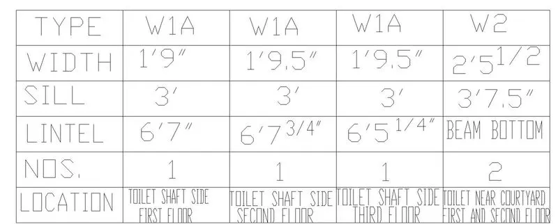
2. Create a window schedule as shown in the figures:
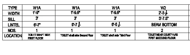
Window Schedule:
INTRODUCTION
The table contains the width,sill and lintel height,their numbers and respective location for different types of beams.
PROCEDURE
1] Make the table
2] Using multiline fill the following data
3] Using multiline,give the heading "Window Schedule"
RESULT
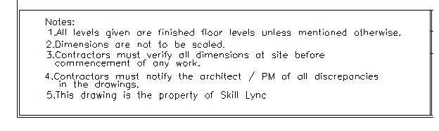
3. Create the drawing template as shown in the figure:< Use the Notes as in the figure>

PROCEDURE
1] Make the following table
2] Using multiline text type the data given and place it in the first column.
3] Type the following in rest of the rows and columns as shown.
RESULT

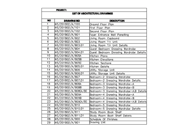
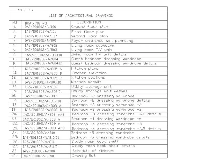
4. Create the list of drawing schedule as shown in the figure:
PROCEDURE
1] create the table by rectangle command.
2] divide the table by rows and columns with proper dimensions.
3] Add text and fit it according to the row size.
RESULT
5. Create the Beam detail as shown in the figure and provide text wherever given.
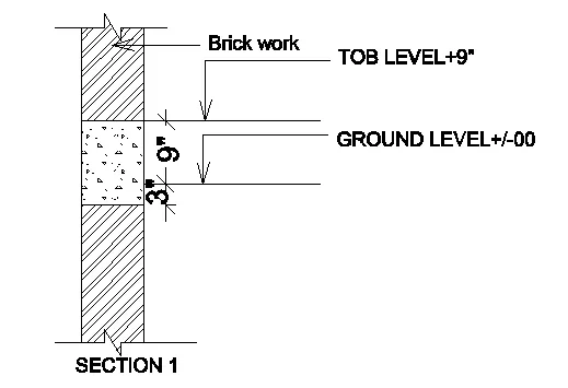
PROCEDURE
1] Make two parallel lines 45" long at a distance of 6" from each other.
2] using line command draw the breakline at top and bottom.
3] Make the horizontal lines as shown.
4] Give the required labelling using leader and multitext
5] Give the hatching of brickwork and concrete as shown
RESULT