creation of base bracket plastic componemt
Objective: Create the Base Bracket Plastic component through the given Class-A surface. To begin with, the tooling axis for the given Class-A Surface should be created meeting the requirements of the draft angle and at the end perform the Draft analysis on the model.
Tooling Axis: The direction which the core and cavity opens.
Styling Class: It distributing the part according to the stage or positions. Styling class are divided in to 3 categories
- Class A
- Class B
- Class C
Class A:
In product, all outer parts are comes under the class A.
Class B:
In product, inner parts are comes under the class B.
Class C:
Intermediate parts which helps for joining the outer and inner parts.
Process for Base bracket:
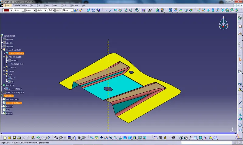
Initially creating a geometrical set under geometrical set with a name of “Tool Axis”,” Class A”, “Class B”, “Class C” and “join”.
Tool Axis:
Define work object on tool axis and creating tool axis for exiting surface model with help of point and axis commands to the centre of the surface.
Point: point-circle/ellipse/sphere centre-surface ellipse-ok.
Axis: axis line-point and direction-Z direction-length of axis (90, -90)-ok.
Draft Analysis Class A:
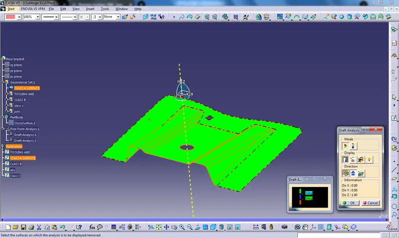
Performing the draft analysis check whether our part model created in cad can manufacturable or not.
Material restrict Mode: view mode-Customise-Shaping, material-ok
Draft Analysis: Insert- analysis- draft analysis-set up colour (3,0) and colour(green, blue, red)- place the compass in axis-define compasses- unlock draft- ok.
Class B:
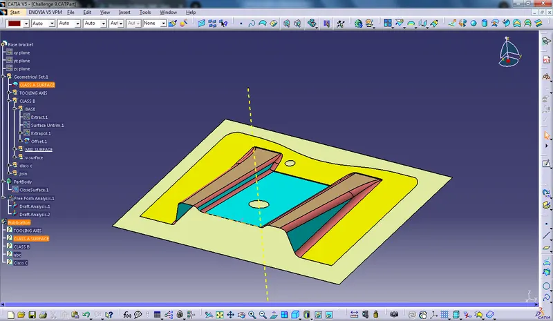
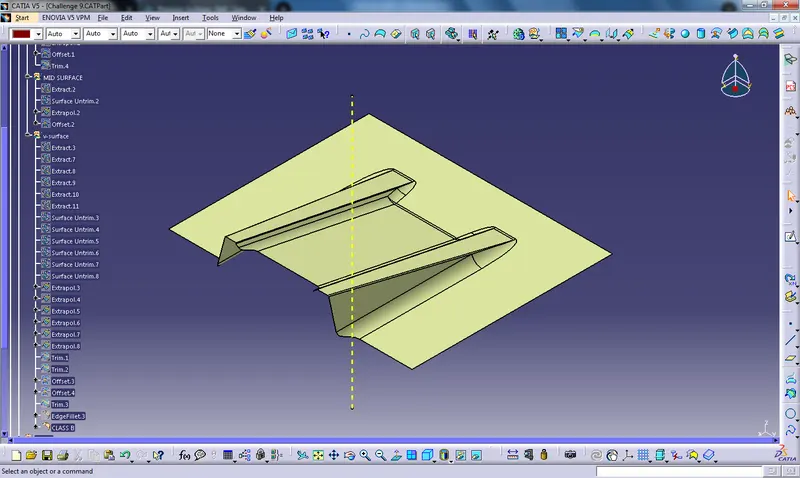
Creating the replica of the class A face with offset of 2.5 mm distance for class it contains 3 geometrical set “Base”, “Mid Surface”, “V-surface”.
Base:
Creating the Base surface with an offset of 2.5mm with help of below commands and finally gets this surface as shown in fig.
Commands Applied: Extract, surface untrim, extrapolate and offset.
Mid surface:
Creating the Mid surface with an offset of 2.5mm through class A with help of below commands and finally gets this surface as shown in fig.
Commands Applied: Extract, surface untrim, extrapolate and offset.
V-surface:
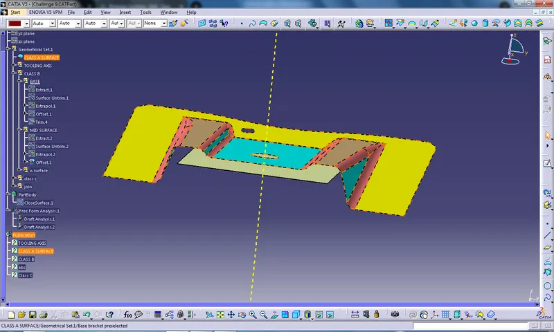
Creating the V-surface with an offset of 2.5mm through class A with help of below commands and finally gets this surface as shown in fig.
Commands Applied: Extract, surface untrim, extrapolate, trim and offset.
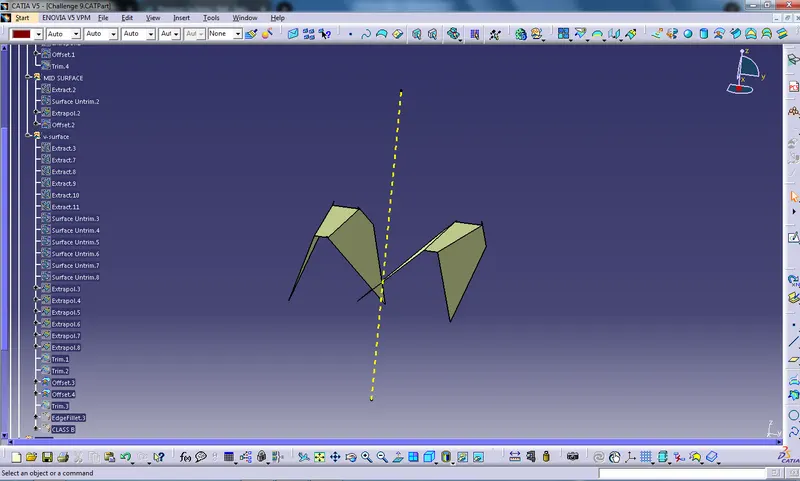
Now combine Base, Mid Surface and V-surface and remove extra material through trim command and set corner edge through edge fillet. Finally, Class B generated, as shown in fig.
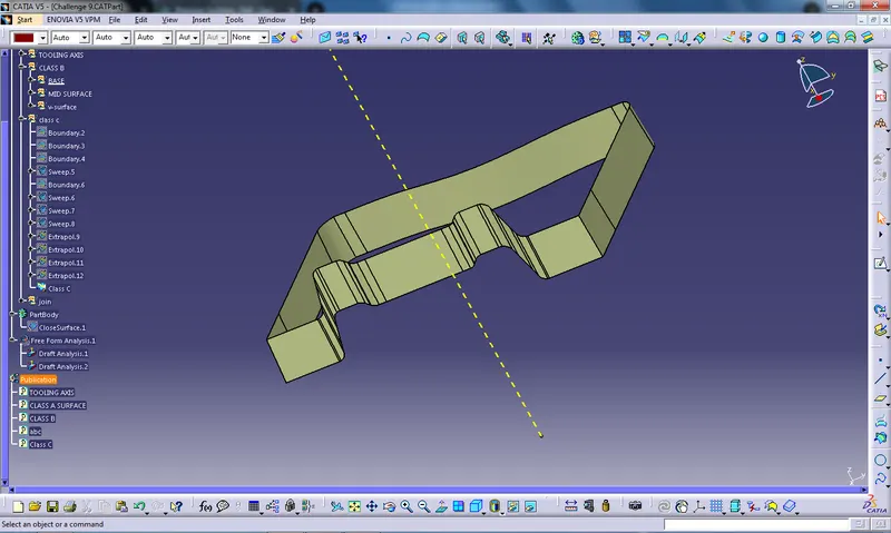
Class C:
Creating a the joint surface between Class A and Class B with help of below commands and finally gets this surface as shown in fig.
Commands Applied: Boundary, sweep, extrapolate and trim.
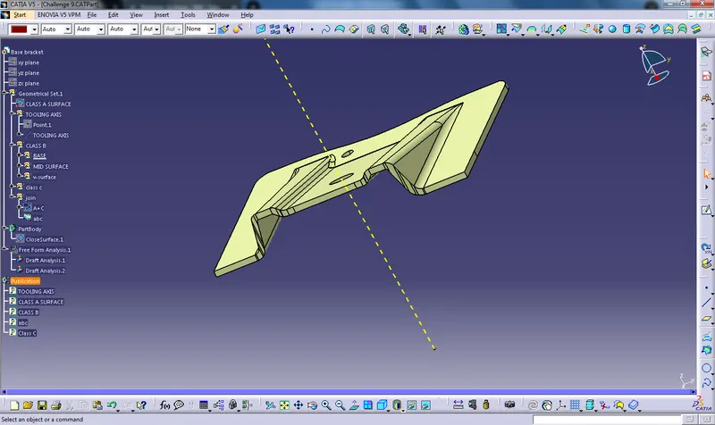
Join:
Now, we created class surfaces individually now combining the surface under join through join and trim Command. And finally get Base bracket surface with completed Closed as shown in fig.
Published:
It separates from the main structure simply disconnect from main branch create like a final part.
Shaping with edge: Mode- shaping with edge- ok.
Published: Select tool axis line, Class A, Class B, Class C and ABC-Insert- Publication- Ok.
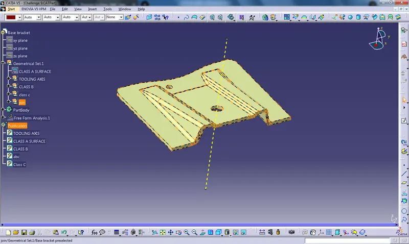
Part Body:
Simply says that add the material into the surface to get base bracket part. Finally, get base bracket shape as shown in fig.
Commands Applied: Part body- Select ABC- closed surface- ok.
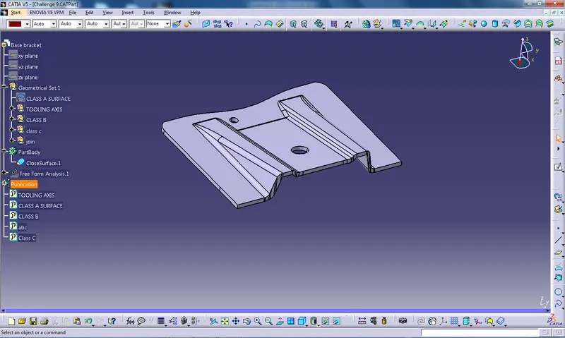
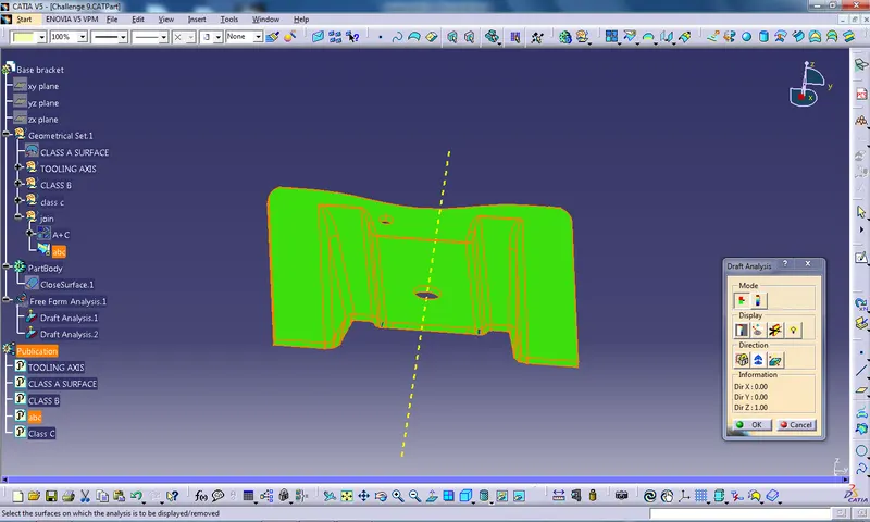
Draft Analysis for ABC:
Material restrict Mode: view mode- Customise- Shaping, material -ok
Draft Analysis: Insert- analysis- draft analysis- set up colour (3,0) and colour(green, blue, red)- place the compass in axis-define compasses- unlock draft-ok.
Geometrical Views:
Isometric View:
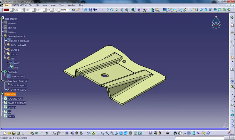
Front View:
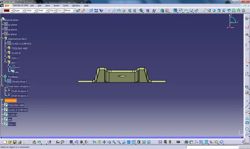
Top view:
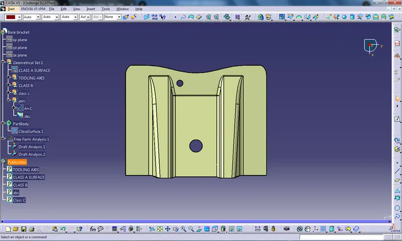
Side View:
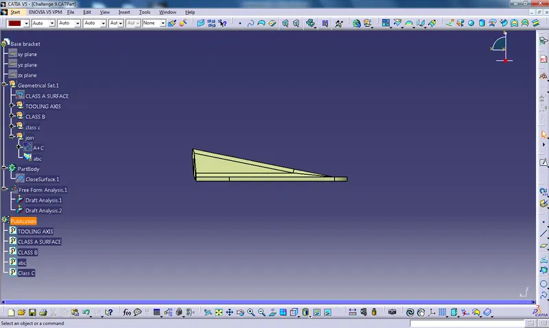
Result:
Creatation of Base Bracket Plastic component through the given Class-A surface and tooling axis for the given Class-A Surface and performed the Draft analysis is done sucessfully.
Conclusion:
By observing the Draft Analysis of ABC, finally concluded that the base bracket plastic component is manufacturable.