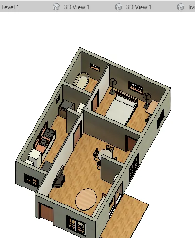
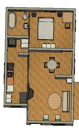
Creating Walls, Partition walls and Floors for a residential layout using REVIT
CREATING FLOOR ,WALLS AND APPLYING MATERIALS AND CHANGING PROPERTIES,COPYING AND PASTING OF MODEL,INSERTING INTERIOR PARTITION FOR CREATING ROOMS AND PLACING COMPONENTS IN EACH ROOMS
Tools used:
a. Floor
b. Wall
c. Edit
d. Property Browser
e. Copy
f. Paste
g. Load family
h. Levels
1. Aim : -To create floor and assigning material and thickness using property browser.
-Aligning it with the grids.
Procedure:
Step 1: Click on the floor created .( from architecture tab- floor -pick lines and select the boundary lines)
Step 2: Click on edit type (generic 150mm floor is created) , then type properties dialogue box appears.
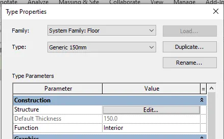
Step 3: Click on duplicate , enter the name as "new floor".
Step 4: Type properties dialogue box appears.
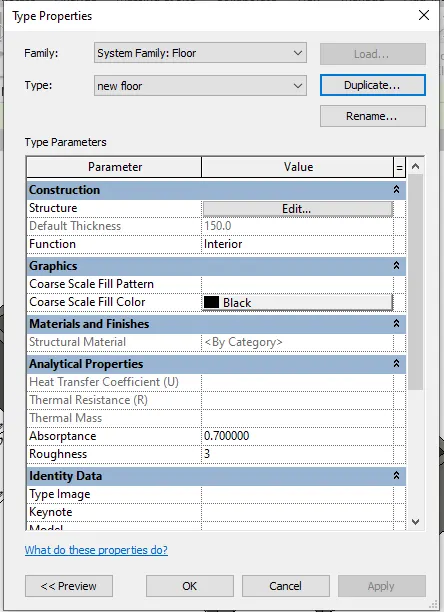
Step 5: Click on edit in strcuture.
Step 6 : In edit assembly dialogue box, we can change the thickness and material, thickness is kept 150mm.
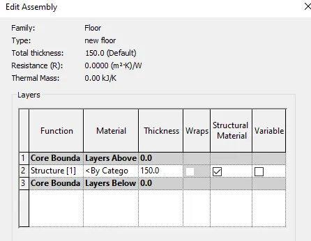
Step 7 : Click on by category under material tab
Step 8 : Select oak flooring from the material browser and click ok.
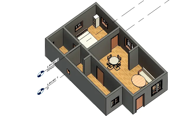
Step 9: The wall is placed in aligned to grid 1.
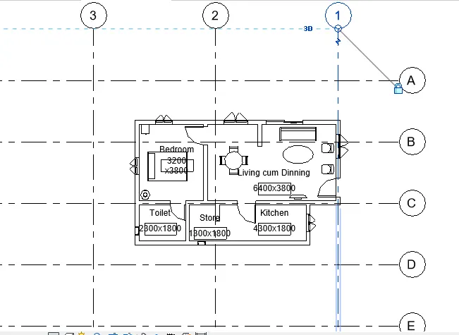
Result:
Floor is created and material is assigned.
The created plan os aligned with the grids
2. Aim : -To add walls
-Add material of wall and thickness
-Make top and bottom of wall constrained
Procedure:
Step 1: Walls are created.
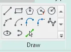
Step 2: to change the boundaries of wall click on edit profile in modify tab , click draw line or pick lines , then do the necessary changes.
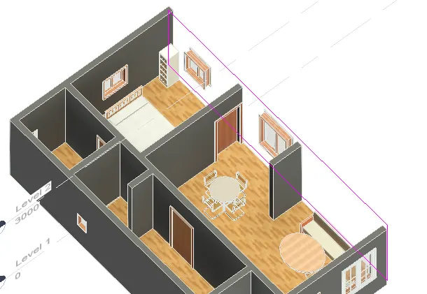
Step 3: As I do not want any modification for wall , I havent changed it.
Step 4: From architecture tab , in doors -load family and double door sliding dooris loaded.
Step 5: Place the door in the living room .
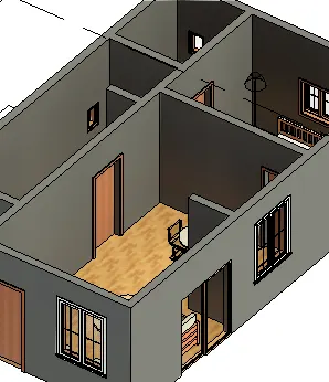
Changing wall properties
Step 6: Select the wall , go to property manager - edit type - create duplicate so we can edit the properties.
Step 7 : Give the name as wall ,seelct edit from the structure tab
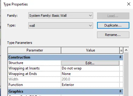
Step 8: In the edit assembly dialogue box, click tab under material , tickness is not chnaged (200mm) , to chnage clcik on the thockness tab
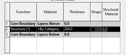
Step 9: From the material browser , select concrete masonry unit as material, we can it under tha appearance tab.
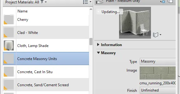
Step 10 : Click ok.
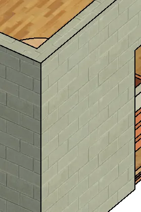
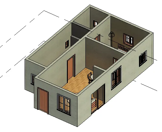
Step 11: Select the walls and look at property browser on the left.
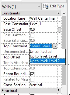
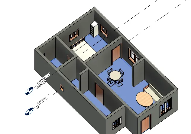
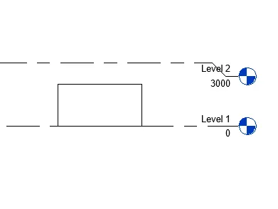
Step 12: The base constain is in level 1 , in the top constrain select level 2 (3000mm)
Result:
- Wall is created
- Materail concrete is selected
-Top and bottom of wall are constrained
a. (i) If walls are connected to level , if we change the height of level , the walls if connected will automatically adjust to that level.
eg : In floor plan , click on architectural tab- wall

- In the top also we can select the level, or after creating the wall seelct it and go to properties and change it to level 2
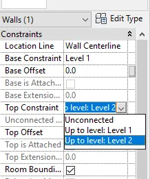
- if we go to the elevation view we can see that the elevation of wall is created from base level1 to top as level 2.
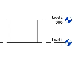
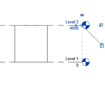
- If we change the value of level 2 to 4000, we can see that the wall created also moves to a height of 4000.
(ii) On the other hand , if the wals are un connected , if we are changing the level, the walls remain in the height given during drafting.
eg: Go to property browser by selecting the wall and change the top constrain to unconnected.
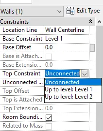
- Now the initial level is 4000mm .
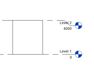
- If we change the level to 3000mm, we can see that the wall remains unmoved.
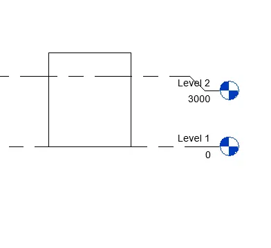
- So connecting the wall is convenient as it will be moved with the level.
b. For modelling height will be the convenient option.
- When we create a wall , there will be two options available.

- Depth : If we are giving depth , it indicates height downwards from the level selected.
- Given a depth of 2000 from level 1
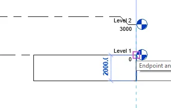
- Height : It indicates the height above the level selected.
- Given height of 2000 from level 1.
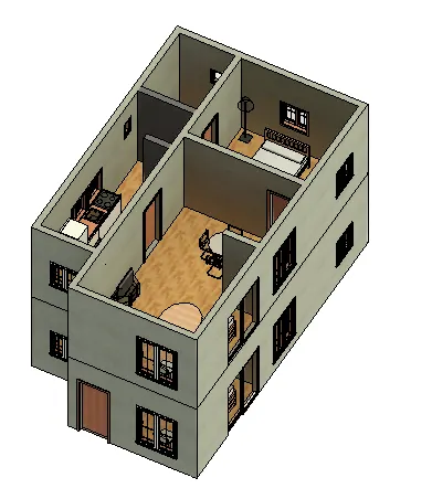
3. Aim : Use of copy and paste and aligning the plan to the other levels.
Procedure:
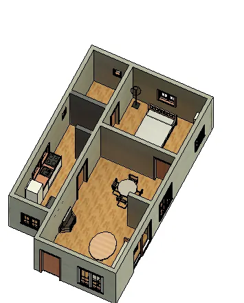
Step 1 : Select the model in 3d view.
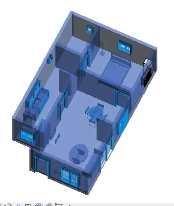
Step 2: Click on copy to clipboard.
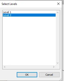
Step 3 : Select Paste and select aligned to selected levels.
Step 4: Select level 2 , and click ok.
Step 5: Delete the top door.
Result:
The ground plan is copied and paste and aligned to the second level.
4. Aim : To use interior partition wall to seperate rooms\
Procedure:
Step1: From the architectural tab , select wall -architecture
Step 2 : Select interior partition wall
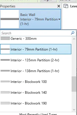
Step 3 : Place it in plan view
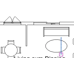
Step 4: Place each of partition wall to create different rooms
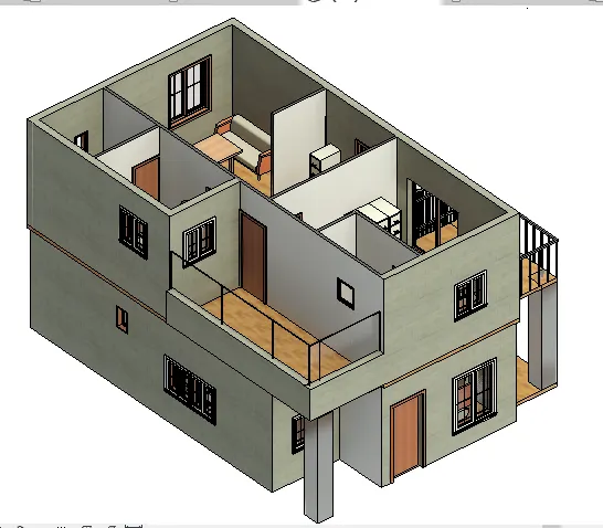
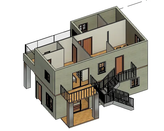
Step 5: Create a patio from the living room by architecture -floor- draw line, draw the outline of the floor.
Step 6 : Create stairs by clicking on stair option from outside
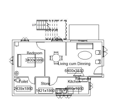
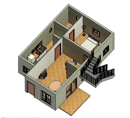
Step 7: For creating bedrooms in first floor , use wall tab -generic 200mm and interior wall.
Step 8: By door in the architecture ,place the doors.
Step 9 : For windows, also go for architecture tab -windows.
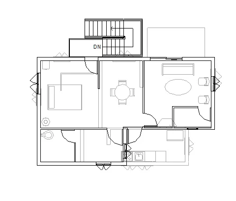
Step10 : Create room tags by clicking on room in architecture tab.
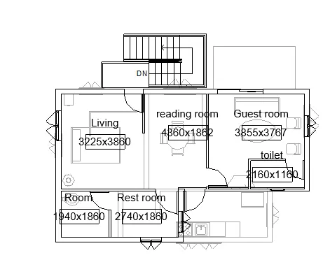
Level 2 plan
Step 11: Create floor for open terrace in level 2.
Step12: Click on floor and select draw lines and draw the boundary.
Step 13: Similarly create floor for pation from the guest bedroom.
Step 14: Select the floor and apply the material.
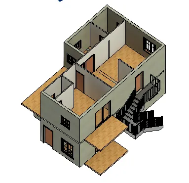
Step 15: Create curtain wall exterior glazing above the half wall.
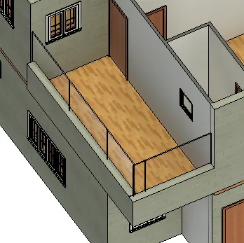
Step 16 : Create handrail for the patio in the guest bedroom.
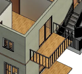
Step17: Create column below the patio and the open terrace.
Result:
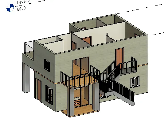
- Partition walls are used to create rooms
- Stair is created for the acess to first floor.
- Curtain wall is used for open terrace.
- Patio is created.
5. Aim : Adding of componentsto the model
Procedure:
a. Placing of doors and windows
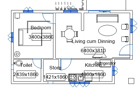
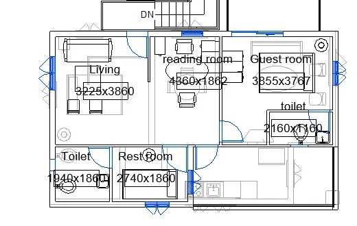
Step 1: From the architecture tab, click on door and craete doors for each rooms .
Step2 : From architectural tab , click on windows and place the windows in all rooms.
Step 3: Place ventilators for the toilet.
Step 4: place double siliding door for the living area.
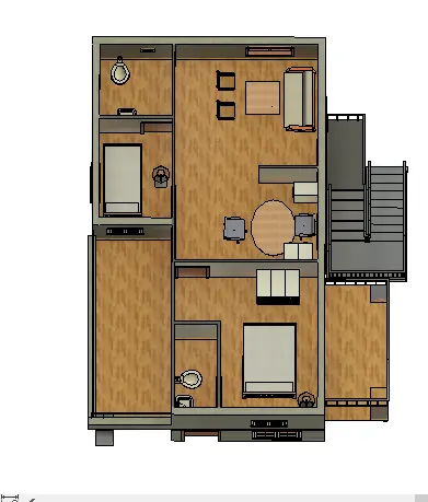
The selected items shows the doors and windows.
Ground floor First floor
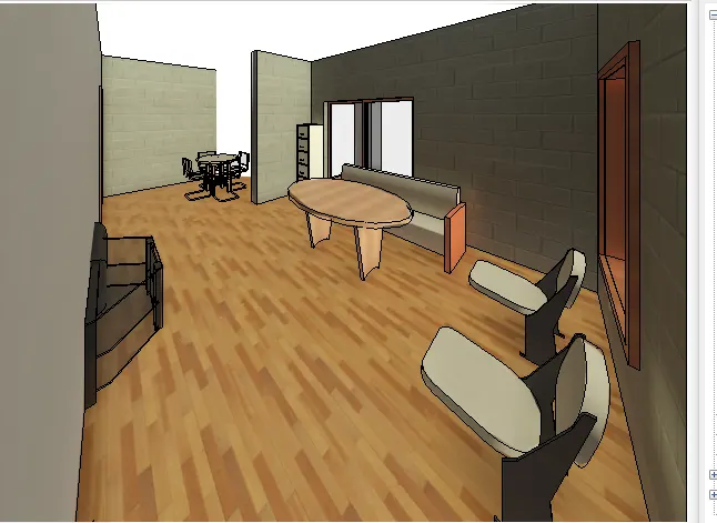
b. Living room:
Step 5: In architectural tab, click on place components.
Step 6: Click on load family to load the sofa ,couch table, Tv desk and shelf cabinet.
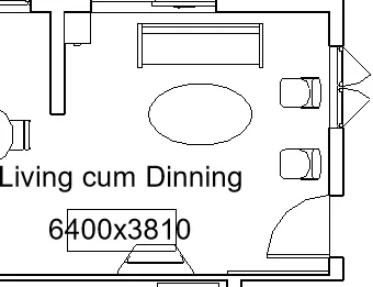
Step 7: Place the camera to get the living room 3d view.
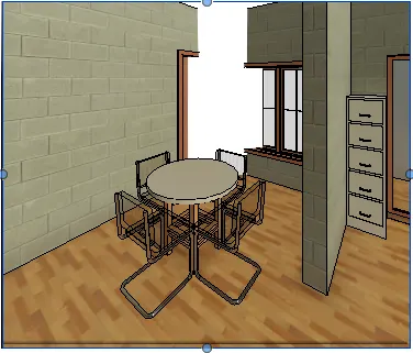
c. Dinning room:
Step 8: Place table round with chairs in the dinning room .
Step9: Load it from the family .
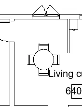
Step 10 : Set the camera view for dinning.
d. Bedroom:
Step 11: click on place a component from the architectural tab
Step 12: Load family - load bed , table, chair, light ,cabinet and place it in the room.
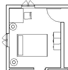
Step 13: Set the camera
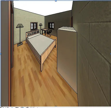
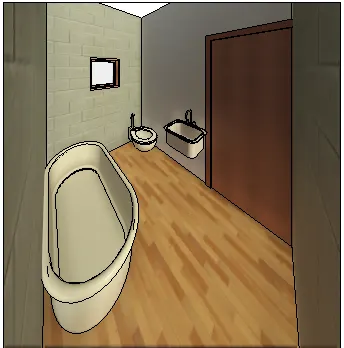
e. Rest room
Step 14: In the restroom from the plumbing tab in load family load sink, bath tub, water closet.
Step 15: Insert in the drawing by place component option in architectural tab.
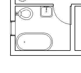
Step 16: Set the camera for 3d view.
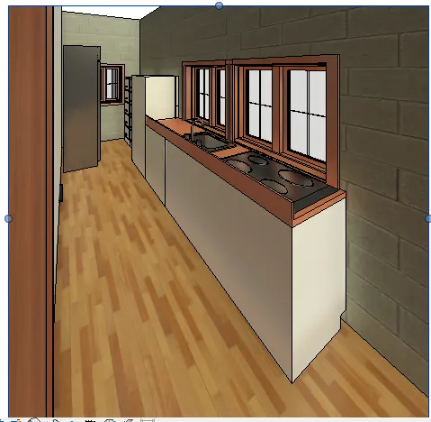
f. Kitchen
Strep 17: In load family under speaciality equipments kitchenette is found -cabinet are also included along with hood and hob.
Step 18: Refrigerator is also loaded from the mid-range folder.
Step 19 : Cabinets are also placed for storage of food items.
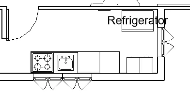
Step 20 : Create camera view for 3d
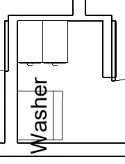
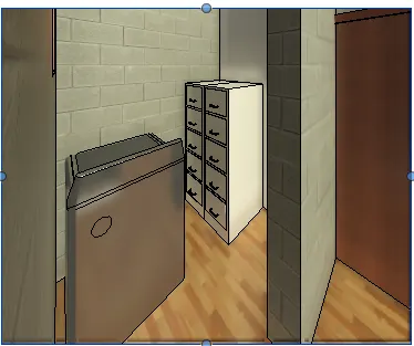
g. Store room
Step 21: Washing machine and storgae cabinet is loaded into the store room.
Step 22: 3d realistic view is made by setting the camera
Result:
Components are placed in each room and 3d view is created.