Creating various 3D Models like Furniture, Footing, Girder, Column drop with panel and Gable Wall in AutoCad
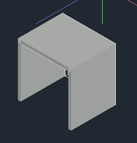
Aim - To create 3D model of furniture
Procedure -
- open Autocad file
- Set the unit as impherical
- Unit set to engineering with precision 0'0"
- Set lim 0,0 and 100,100
- Z enter,A enter for zoom all
- From setting switch to 3D modelling
- Set to top view 2D wireframe
- Draw a rectangle of 3'x3' in xy plane
- Explode the rectangle
- Offet three sides at a distance of 2"
- Enter boundary command and select offset line and make a region
- Similarly repeat the same for other two sides and whole rectangle
- Go to default view by clicking home icon
- select excrude from ribbon and select all region
- Excrude at a height in z axis 2'6"
- Select substract command and select rectangle and then enter
- Select smaller rectangle and enter
- Select union command and select all object enter
- Use linear dimension and measure by switching UCS
Result -
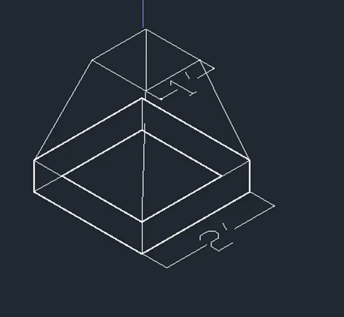
Aim - Create 3D model of Isolated footing
Procedure -
- Set the view to top and 2D wireframe
- Draw a rectangle of each side 2"
- Select offset command and select rectangle and enter the distance as 1'
- Move the default view
- Enter move command select 1'x1' rectangle and move at a distance of 3'
- Select loft command,select two rectangle and enter
- Now excrude the rectangle of size 2'x2' with height 6"
Result -
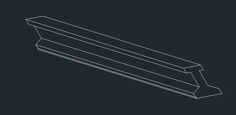
Aim - Createb 3D view of AASTHO type Girder
procedure -
- Set the view to top and wireframe
- Draw a set of rectangle of dimension 10'x6",10'x1'4",10'x1'6",10'x1'
- Now align the rectangle in bigger recatngle using geometric center
- Set the view to SW isometric
- Excrude rectangle upto given height as 10'6" to 1'6"
- Follow the same of remaining
- Align the rectangle upto certain height using move command,move the rectangle 10'x6" at a height of 0,0,1'
- Now tamper last second rectangle by selecting width face,specifying base point and axis enter angle as 15
- Similarly for second rectangle enter angle as 45
- use union command to join the excruded section
Result -
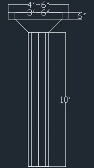
Aim - create 3d model of Drop column with panel
Procedure -
- Select the top view with wireframe
- draw a circle of 1'6"
- Excrude the circle at height 10'
- Move back to top view and draw a rectangle of size 3'6" x 3'6"
- Place the rectangle on circle using onsnap or enter distance s 0,0,10
- Excrude the rectangle at height of 1'
- Select tamper command from solidedit tool and select the face
- Specify the base point and enter the angle as 45
- repeat the same on other side or use loop command in tamper
- Back to top view and draw a recatngle of side 4'6"x4'6"
- Move back to isometric view and excrude at height 6"
- Place the rectangle of top 3'6" recatngle using UCS icon or distance command
- USe union to make object one
Result -
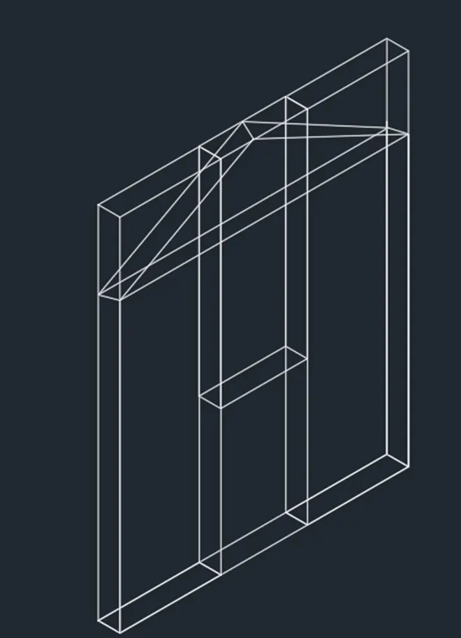
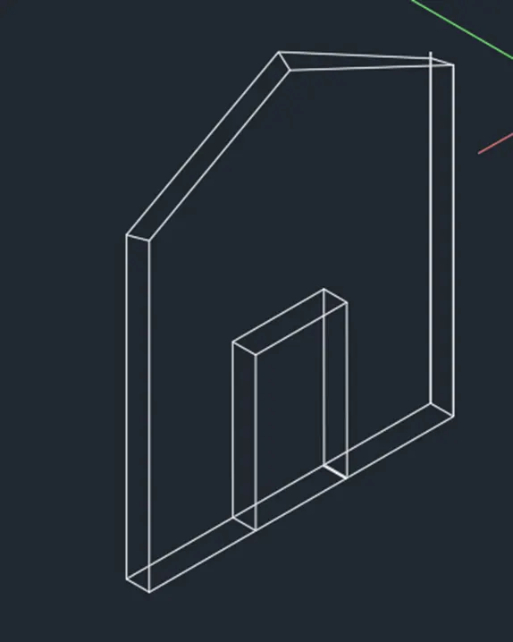
Aim - Create 3D model of Wall
Procedure -
- Set the top view and wireframe
- Draw a recatngle of size 10'9"
- Now explode the rectangle
- Offset the width on both side at a distance of 3.5'
- Enter boundary command and selct point and region
- Set the view to default isometric
- Excrude the corner region upto height 12'6"
- Now move the door rectangle to height 0,0,7'
- Now excrude the moved rectangle upto 12.5'
- Set the view to front and draw a triangle of sides 5.5'and base 10'
- Make triangle as region using boundary command
- Excrude the triangle at a distance 9" towards y axis
- Use presspull to reduce the rectangle wall
- Use union command to join all excruded wall
Result -