Creating various 3D Models like Furniture, Footing, Girder, Column drop with panel and Gable Wall in AutoCad
AIM :-
1 . To create 3D model and view of furniture element
2 . to create 3D model and view of isolated footing
3 . to create 3D model and view of AASTHO type girder
4 . to create 3D model and view of drop column with panel
5. to create 3D model and view of a wall
INTRODUCTION :-
. Autocad is 3d is a powerful CAD software , which is made use of for the architectural style and mechanical design . it has
one of the best toolbox and features to sustain 2D drawings. Nevertheless , when it involve a 3D layout , it is impressive
with it 3D providing attribute that offers enstaional and vivid outputs .
COMMAND USED :-
. UCS
. EXTRUDE
. box
. Union
. subtract
. intersection
. move
. 3d orbit
. loft
. sweep
. boundary
. region
those command are briefly illustrated below
. UCS :- To define your UCS manually , just click two points define the orientation of the x axis to set your UCS based on
the angle of an object in your drawing , such as a polyline ,click the object . as the you move the cursor up and
down you wll see a line extending 90 degree from the object you selected
. Extrude :- Create a 3D solid from an object that enclose an area or 3D surface from an object with open ends . Objects
can be extrude orthogonally from the planes of the surface object in a specified direction or along a selected
path
. Presspull :- The presspull command will extrude a 2D object into a 3D object or extend a 3D surface . when using the
pressspull command with 2D object th e 2D object will remain in the drawing box .
. UNION :- The union command used to combined the selected 2D region or 3D solid by the addition . the selected parts
are combined to form a single region , surface or solid . but we are required to select the parts of the same
object . we can selelct two or more parts to combine it into a single region
. SUBTRACT :- Select the object that you want to keep press enter the selected the object that you want to subtract
Object in the second selection set are subtracted from object in the first selection set
. INTERSECTION :- On the ribbon choose DRAW > apparent intersection snap . on the menu choose tools > entity snap
> apparent intersection snap
. Select the object and subobject you want to move using the following .
methods : press the object and subobject .
. 3D Orbit :- if you press shift + the wheel of the mouse and move the mouse you will jump the into 3D orbit command
without the need to type it
. LOFT :- Create 3D solid or surface in the space between serval cross section . create 3D solid or surface by specifiying
a series of cross section . The cross section define the shapes of the resulting solid
. SWEEP :- Same as loft , int the same path with the same alignment 3D surface or solid is created .
. CONE :- Draw 3D cones . you can run the cone command in any localized version of AutoCAD by typing cone inthe
command line we can even topper surface with smaller radius
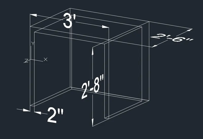
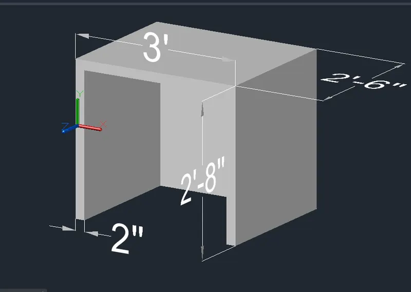
AIM 1 :- To create a 3D model of the furniture element .
PROCEDURE :-
. Open the Auto CAD click on workspace switching and change it to 3D modellig and click onthe home button near the
view cube . set the limits and zoom
. Open AutoCAD select imperial as the units are in feet and inches . go to units command and set it to engineering
so that feet inches be inserted
. Create a box by clicking from the toolbar or box command click on length , give the length as 3' and width 2.6" height
is to be specified give the height as 2'6" .
. select the frony face command UCS give the x and y coordinates in the front face . horizontally and vertcally respective
or click on face and selected the front face . type the command PLAN so that the front face is aligned
. Draw a line 2" from tye right side of the front view . by rectnagle command draw a rectangle the line created earlier
now with command 3D orbit the object and selected the rectangle .
. Extrude the rectangle to -z axis 2'4" leaving 2" thickness . now the give command Subtract select the larger object
then the smaller extrude rectangle in 2nd wireframe model .
. dimension sre given by dim linear command by switching the UCS .
RESULT :-
. The 3d model of furniture element is created .
AIM 2 :- To create a 3D model of isolated footing .
PROCEDURE :-
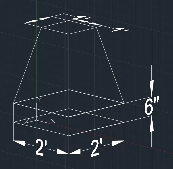
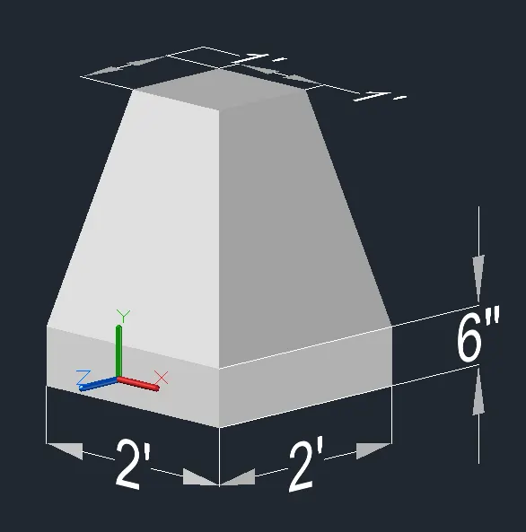
. Create a rectangle of 2'x2' on the top view . create another rectangle of 1'x1' on th top view .
. with command 3do , 3d orbit the view to a suitable one . with M move command move the small rectangle of 1'x1' by
in z+ direction with ortho on .
. click on the loft from the home toolar and select the two rectangle to loft .
. Again go to the top view and create rectangle on top of the bigger rectangle of same size . click on extrude from the
home toolbar and select created rectangle and give the extrude height as 6" and the direction of extrusion is pointed
by the mouse .
. By using UCS command give the dimenssion .
RESULT :-
. The 3d model of furniture element is created .
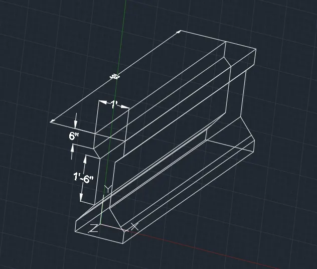
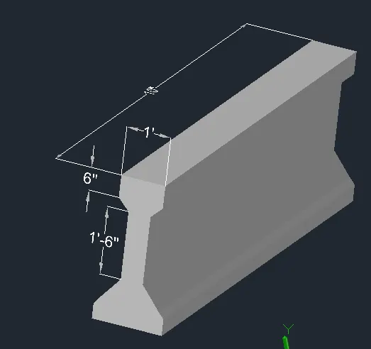
AIM 3 :- To create a 3d model of AASTHO type girder using AUTOCAD 3d .
PROCEDURE :-
. Click on front view . use command and make the x and y axis in the front view planes .
. then by line command draw the I section with the given dimenssion . command L draw a line of 1 that is the top width o
of the girder
. With the line draw a 6" downward with snap on draw a line from center of 1' and offset 3" on both sides such that the
width of web becomes 6" .
. Give a taper distnace and join the web and the flange . Mirror the same on the other side .
. The web is given a height of 1'6" , offset the distnace 1'6" from the end of tapering of the flange portion . delete the
center line drawn for the offset and also trim off the extra lines in flange .
. Extend the web to the offset line . again offset 6" from the last line and taper the sides . mirror the ataperred portion
delete the centre line draw for the offset and also trim off the extra line in flange .
. Offset should 6" doewnward from the bottom horizontal line to define the height . draw the taper at bottom 1'4" , from
the center draw a line and offset 8" on both sides .
. Extend the web to the offset line .again offset 6" from the last line and taper the sides . mirror the tapered portion to
other side . the side should be tapered such that the bottom should be 1'6" draw a centre line and offset 9" on both
sides then join the taper
. Extend the 6" offset line and draw trim resert of lines . draw vertical lin downward and the tapering also .
. With 3d orbit the view and draw a line 10' in z direction click on sweep from the home toolbar and select the section
and then the through which the section to be swept .
RESULT:-
. The 3d model AASTHO type girder using autocad 3d .
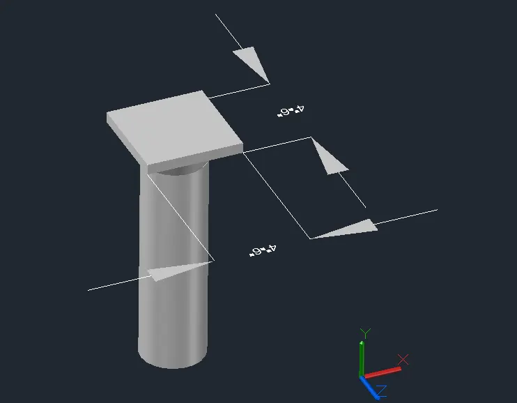
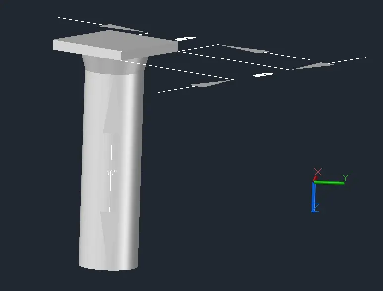
AIM 4 :- To draw the 3d model of a drop column with panel section and show its isometric view .
PROCEDURE :-
. Create a circle of diameter 1'6" in the top view .
. create a region by region command and select the rectangle . extrude it with extrude in home toolbar and give a
distance of 10' .
. create a cone by clicking on cone from the home toolbar . click on diameter and give the base diameter as 1'6"
. click on top radius and give the value as 1'6" and gives the height of the cone as 1"
. Place the frustum of cone on top of the extrude circle i.e the column in the front view with snap option place such that
centre of two object coincides , also place the centre of frustum with center of column in the top view .
. in top view create a rectangle of dimension 4'6" x4'6"
. extrude it to a height of 6" .
. move rectangle drawn over the cone .
. move rectangle drawn over the cone .
. in the tp view place the rectangle at the center of cone and also adust in the front view of give move command and give
the coordinates as 0,10,0 the rectangle is at bottom in the front view .
RESULT :-
. the 3D model of a drop column with panel has been drawn section and isometric view is also shown .
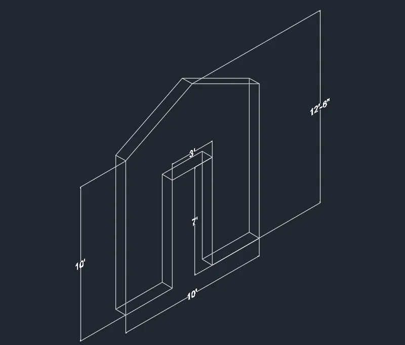
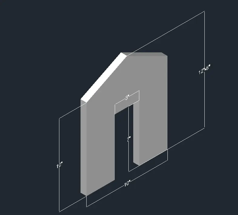
AIM 5 :- To draw a 3d model of wall
PROCEDURE :-
. Draw a rectangle of 10' x 9' . create a line in the centre and offset 1.5" on both sides as 3" is the width of door opening
. use the command BO for boundary and create the region i.e both the region on either side .
. Create a rectangle in place of door in the top view . move the rectangle in z axis at s height of 7" from the bottom .
. Go to front view and draw a line te centre of the moved line of door draw slanting line from the total height from
the total height from the centre line intersecting the edge .
. Go to front view and draw a line from the cemter of the moved line of door . draw slanting line from the total height
from the centre line intersecting the edge .
. Mirror the line to the other side . draw the horizontal line to join
. Trim off the excess line and the centre line and join the triangle with join command . create a region command in the
triangle created .
. select the extrude rectangle and with the help of grip bring it down to level of the triangle based on both sided .
extrude the rectangle of door to a height equal to base of triangle .
RESULT :-
. 3D model of wall is drawn .