Creating various 3D Models like Furniture, Footing, Girder, Column drop with panel and Gable Wall in AutoCad
Q-1. Create a 3D Furniture element as shown in the Figure. Assume dimensions which are missing.
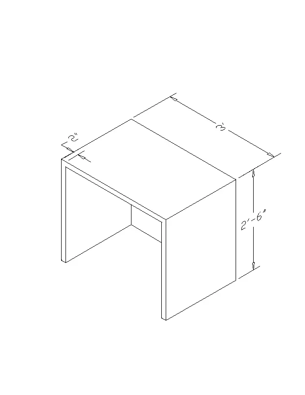
AIM AND INTRODUCTION : 3D Furniture element as shown in the Figure is to be Created assuming dimensions which are missing.
PROCEDURE IN DETAIL :
- Cuboid of outer dimension 3'x2' ( assumed) extruded to the height of 2'-6" is created using BOX command and Extruded command.
- Cuboid of inner dimension 2'-8"'x1'-10"' ( assumed) extruded to the height of 2'-4" is created using BOX command and Extruded command as per the given thickness .
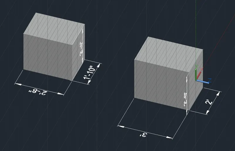
Smaller box is centrally placed over larger box using MOVE command
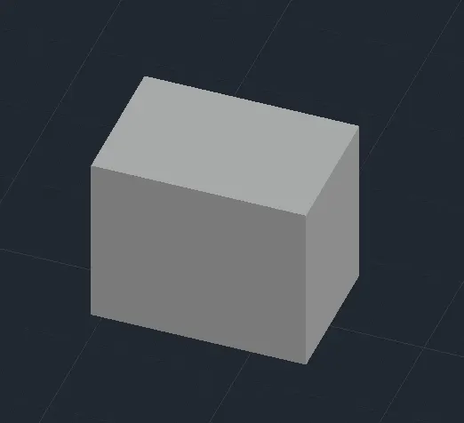
Subtract command is used to remove smaller box from bigger box.
SHADED option is used to view the object as a solid
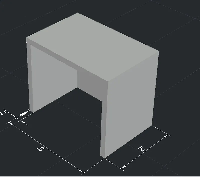
Hidden option is used to see the outer boundaris of the object as shown below-
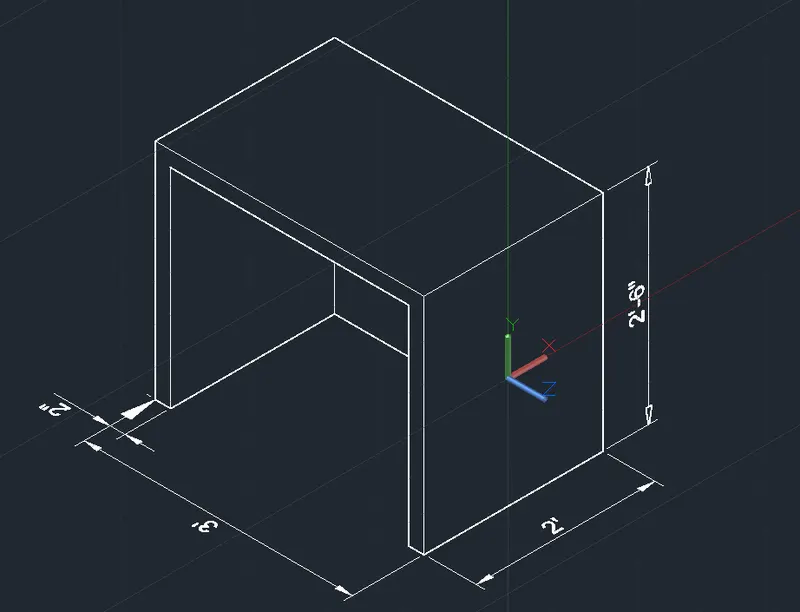
RESULT : Thus 3D Furniture element as shown in the Figure is Created as shown above stage wise snaps and attached .
.DWG file with name ACCH12Q1 is attached for reference..
-------------------------------xxxxxxxxxxxxxx------- END OF Q-1 --------------xxxxxxxxxxxxx--------------------
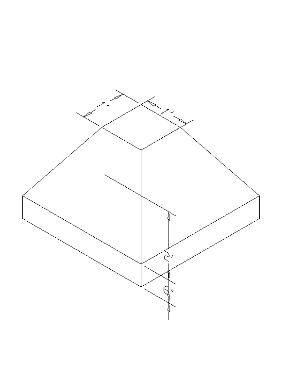
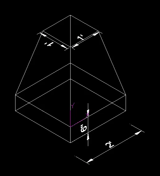
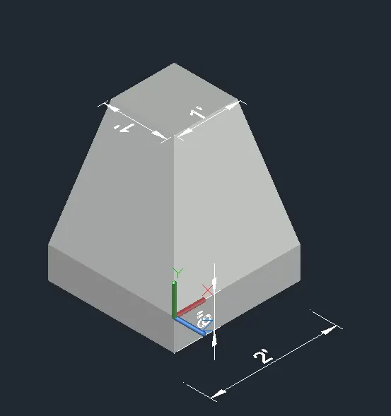
Q-2. Create the 3d Model of an Isolated footing as shown in Figure.
AIM AND INTRODUCTION: 3d model of an Isolated footing is to be created.
PROCEDURE IN DETAIL :
SQUARE OF 2' is created using RECTANGLE ( RECT) command
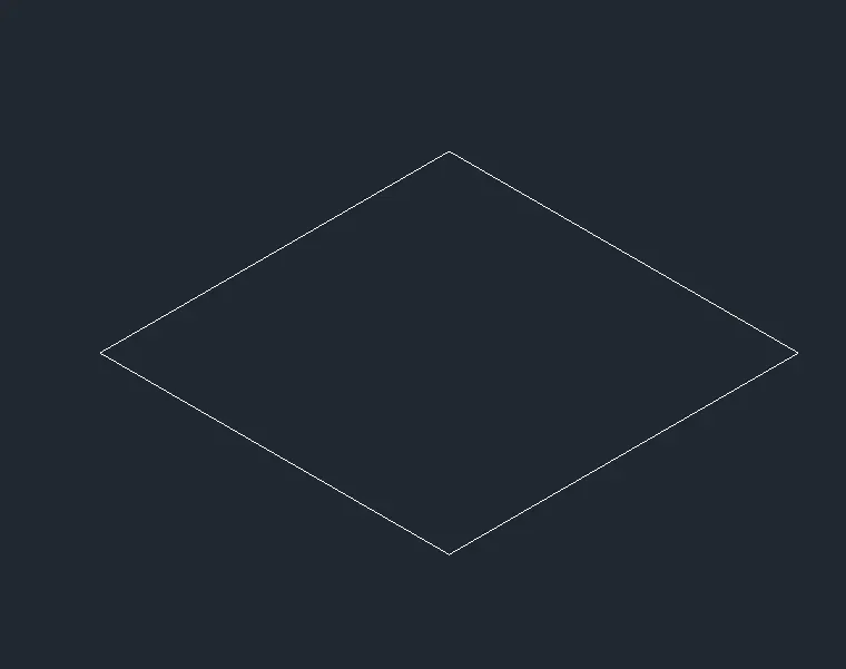
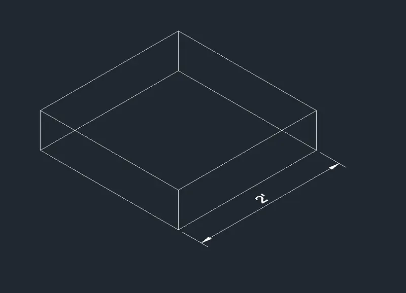
Boundary of square is created using BOUNDARY ( BOUN) command then Extruded to the thickness of 6" using EXTD command.
Pyramid with square base of side 2' and top radious 0.5" or side 1' is created using PYRAMID command then extruded to the height of 2' as shown below using EXT command-
Q 3. Create the 3D view of the AASTHO Type Girder.
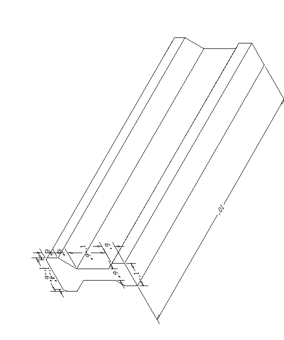
AIM AND INTRODUCTION : 3D view of the AASTHO Type Girder is required to be created
PROCEDURE IN DETAIL :
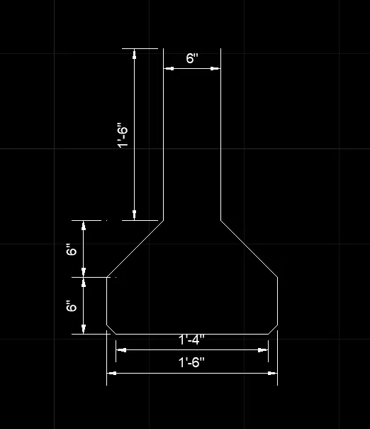
- Line of length 1'-4" is created using LINE command
- Chamfering of 1"x1" is created using line command
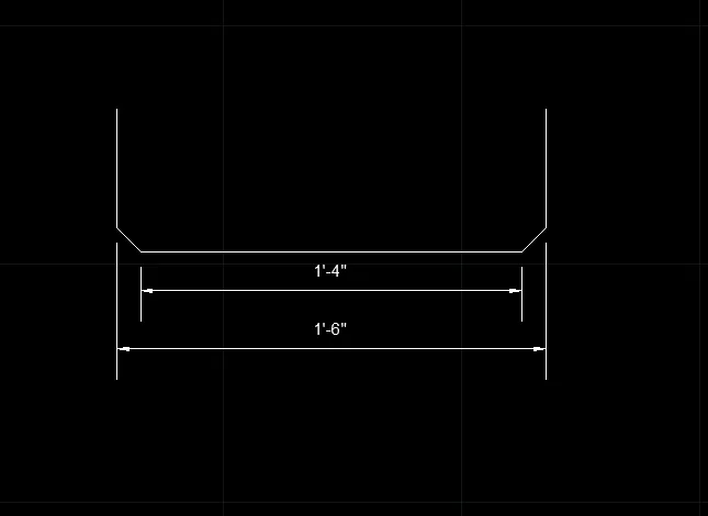
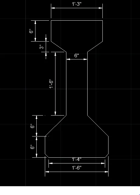
Entire cross-section ( Bootom flange and web)with given dimension is created using line command , offset command and Mirror command
Top flange is also created using above commands as shown below-
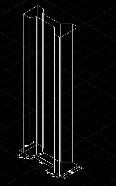
`Section is then extruded to a height of 10' as shown below-
Below is shaded view of I-section-
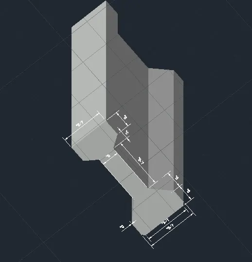
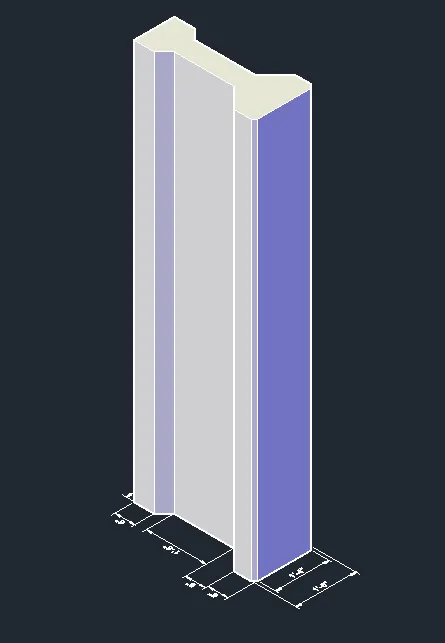
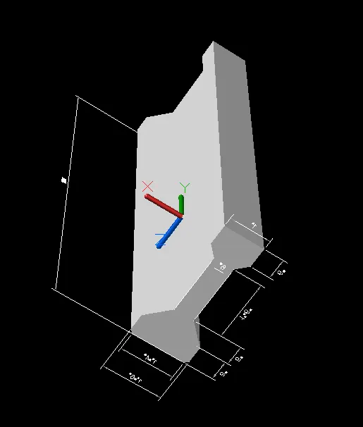
RESULT : Thus 3D view of the AASTHO Type Girder is created as above and its DWG file is also attached.
----------------------xxxxxxxxxxxxxxx-------------- END OF Q-3 -------------------------xxxxxxxxxxxxxxxxxxxxxx
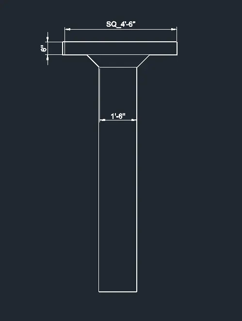
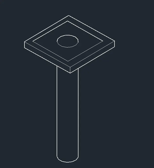
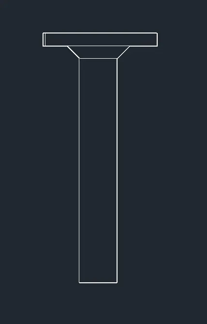
Q-4. Create a 3d Model of a drop column with panel as shown in section and isometric view.
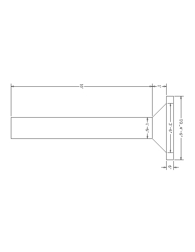
AIM AND INTRODUCTION : 3d Model of a drop column with panel as shown in section and isometric view is to be created.
PROCEDURE IN DETAIL :
- Square of side 4'-6" is created using RECTANGLE ( REC) command then extruded to the thickness of 6" using EXT command.
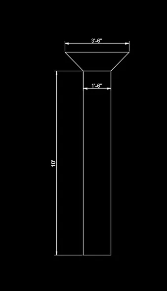
- Another part of the of the drop column is created using PYRAMID command with base side 3'-6" and top radius 9"or side 1'-6" then extruding it a height of 1' .
- For Column circle of dia 1'-6" is created using CIRCLE command
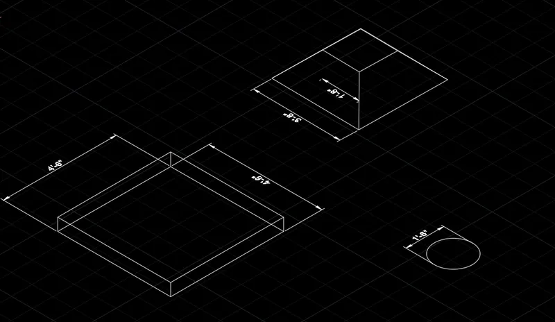
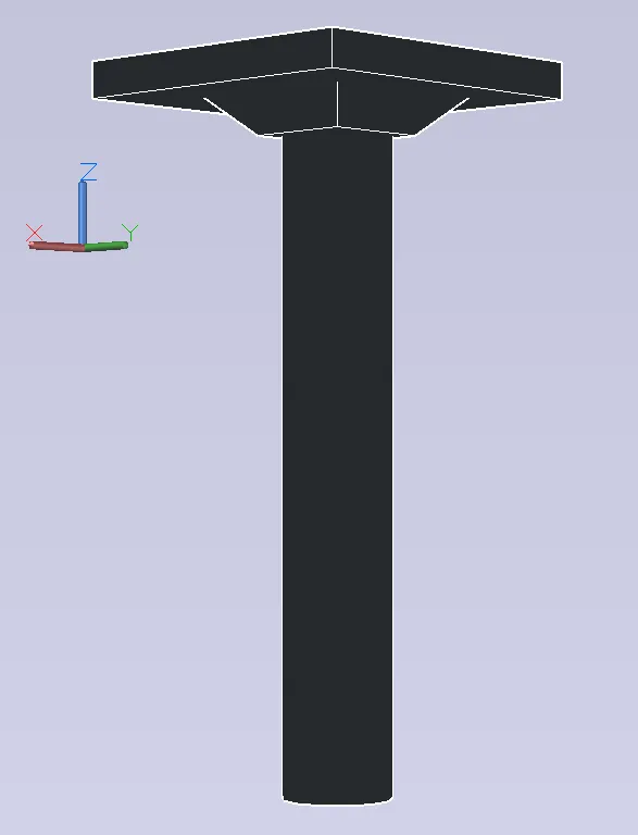
All the three componens of the drop column are placed one over the other as shown using MOVE command-
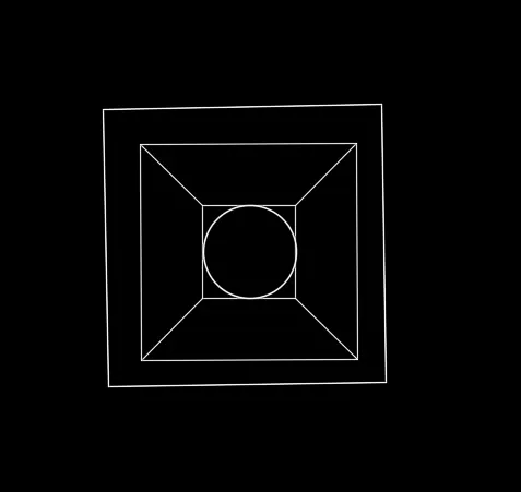
circle is extruded to a depth of 10'
All the components are combined together using UNION command
Below is isometric view of Drop column-
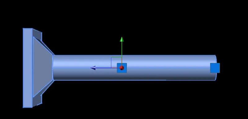
Conceptuall view of drop column-
Shaded view of drop column-
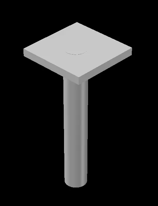
RESULT : Thus 3d Model of a drop column with panel as shown in section and isometric view is created .
.DWG file with name ACCH12Q4 is attached for reference.
-----------------------------xxxxxxxxxxxxxxx---------- END OF Q-4 -------------xxxxxxxxxxxxxxxxxx-----------------------
Q-5. Create the 3d model of a wall as shown in Figure. Consider wall thickness as 9”.
Straight height of the wall is considered as 10'
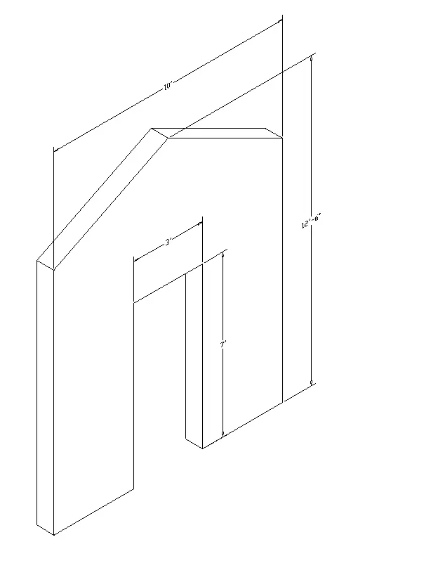
AIM AND INTRODUCTION : 3d model of a wall as shown in Figure as per given dimension is to be created.
PROCEDURE IN DETAIL :
Wall as per given dimension is created using following command -
- Line command
- Offset command
- Trim command
- DimA command
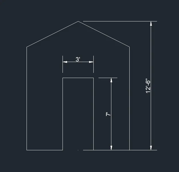
Region is created using REG command then Extrude command is used to extrude the wall to the thickness of 9" as shown below-
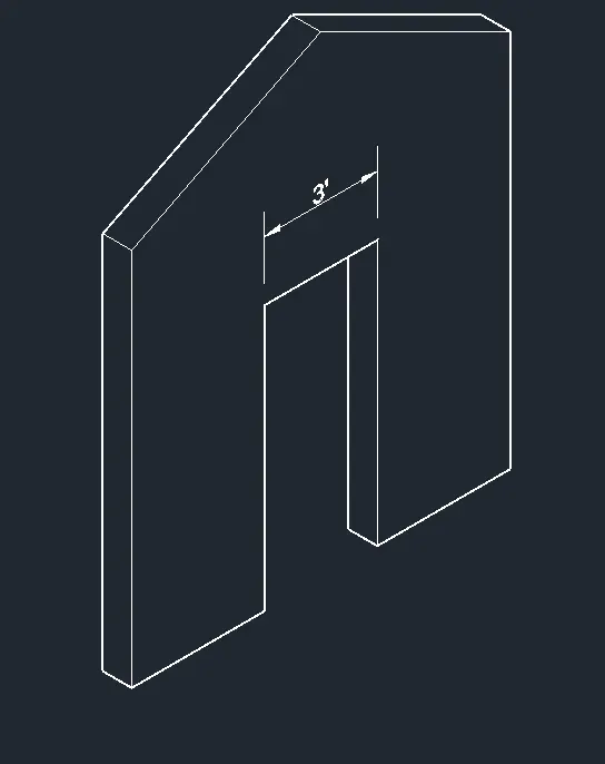
RESULT : Thus,3d model of a wall as shown in Figure as per given dimension is created.
.DWG file with file name ACCH12Q5 of the wall is attached for reference.
-----------------xxxxxxxxxxxxxxxxx--------------- END OF Q-5 -------------------xxxxxxxxxxxxxxxxx----------------