Creating various 3D Models like Furniture, Footing, Girder, Column drop with panel and Gable Wall in AutoCad
AIM:
- To create various 3D Models like;
- Furniture,
- Footing,
- Girder,
- Column drop with panels, and
- Gable Walls in AutoCAD.
USED COMMANDS:
- UNITS
- LIMITS
- LINE
- PLINE
- RECTANGLE
- OFFSET
- COPY
- MOVE
- SUBTRACT
- EXTRUDE
- REGION
- UCS
- BOX
- UNION
- BOUNDARY
- 3D ORBIT
- LOFT
- CONE
- MIRROR
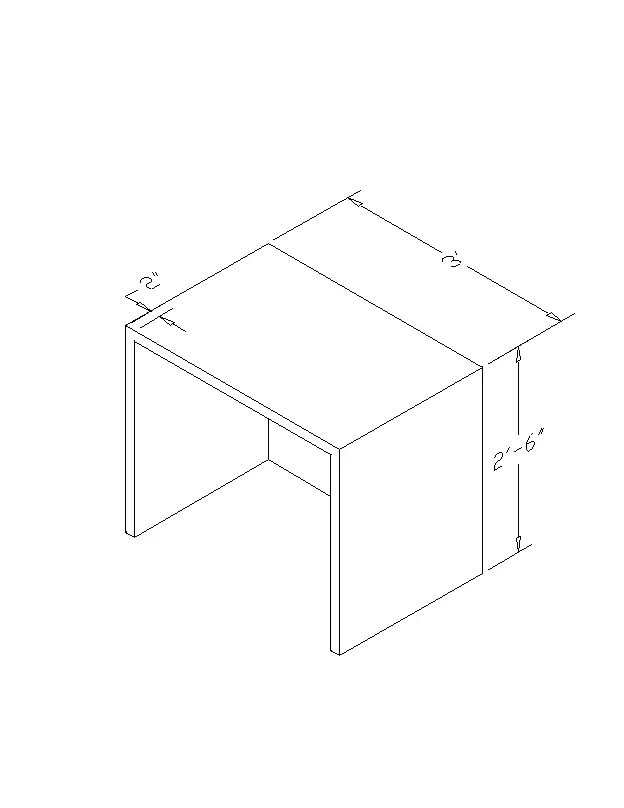
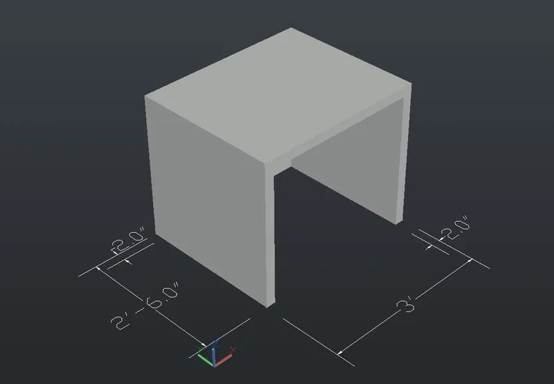
1. Create a 3D Furniture element as shown in the Figure. Assume dimensions which are missing.
AIM:
- To create a 3D model of the furniture element.
PROCEDURE:
- Open a new AutoCAD file and set the unit as feet and inches
- Create the appropriate layers for working on it
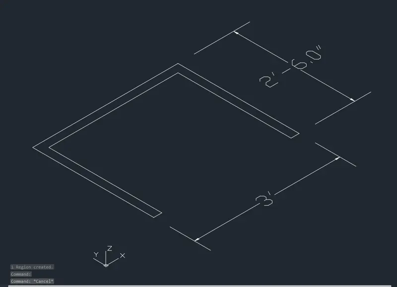
- Select the box from the toolbar, create it of length 3' and width 2'6" and height 2'6" in the top view
- Draw a line 2" from the right side and the front view
- Command rectangle and draw it as a dimension of 32" and 2'4"
- Move the rectangle
- Extrude the rectangle in the Z axis of 2'4"
- Dimensions are given by dim-linear

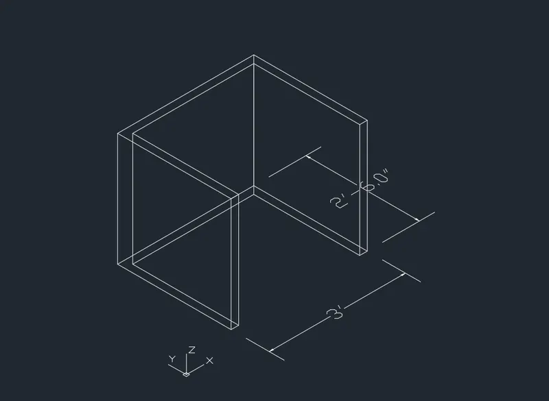
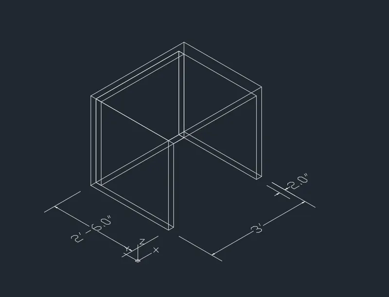
RESULT: Created the 3D model of the furniture element
------------------------------------X-----------------------------------
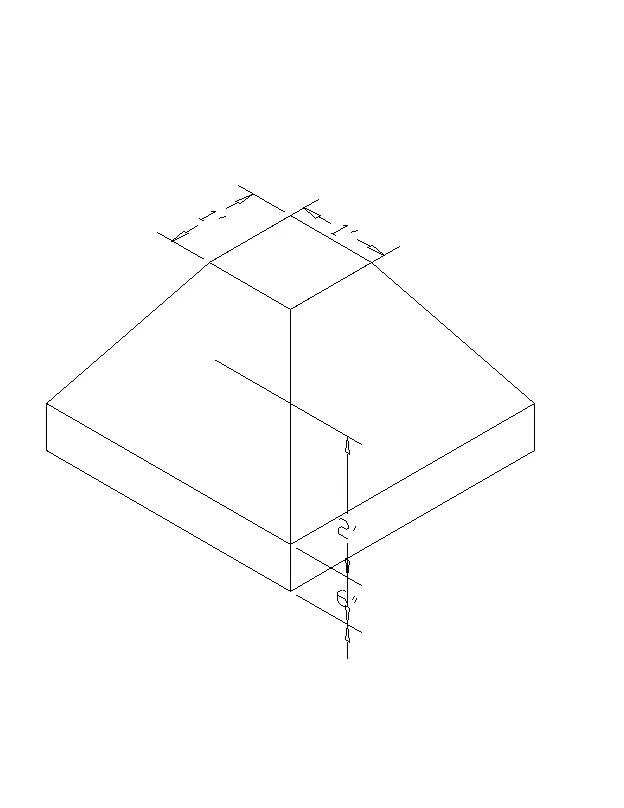
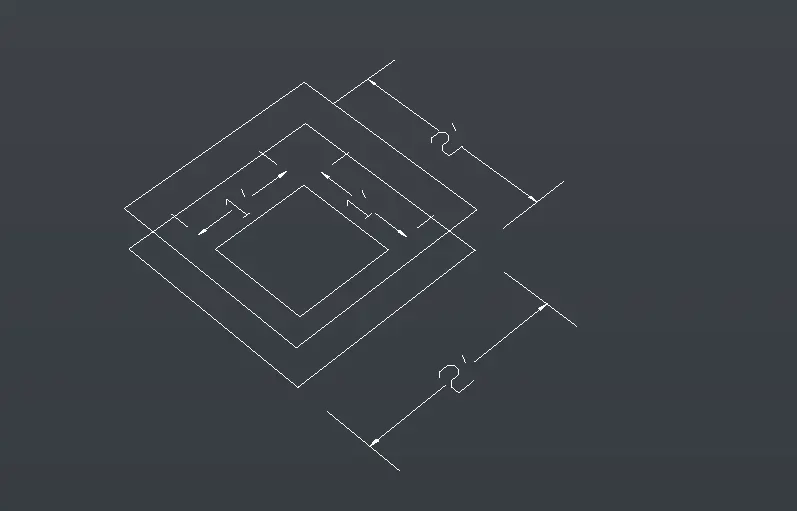
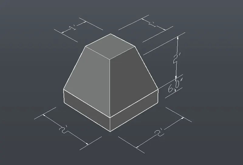
2. Create the 3d Model of an Isolated footing as shown in Figure.
AIM:
- To create a 3D model of isolated footing
PROCEDURE:
- Open a new AutoCAD file, set the unit as feet and inches
- Create the appropriate layers for working on it
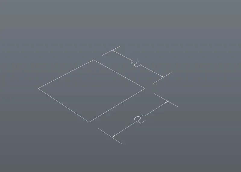
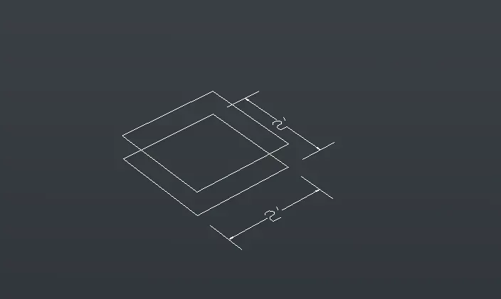
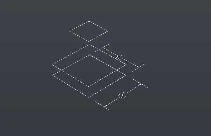
- Command rectangle of 2'x2' on the top view. Offset inward 6"
- Command 3dorbit to view the suitable position
- Command move command small rectangle of 1'x1' by 2' in Z direction ortho on
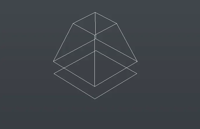
- Command the loft toolbar and select the two rectangles to loft
- Go to the top view and create a rectangle of the same size
- Extrude height is 6" and the direction of extrusion is pointed by the mouse
- Give dimension
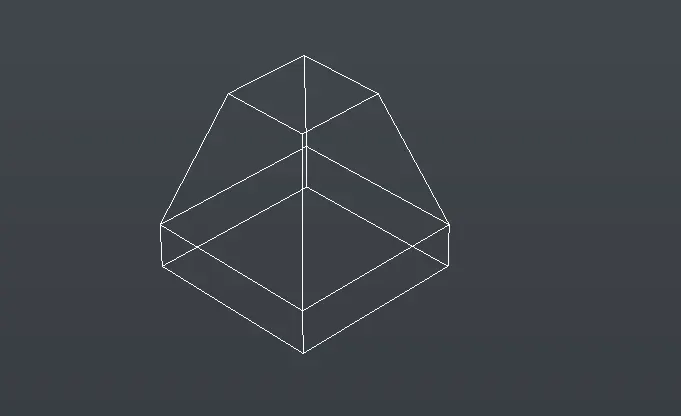
RESULT: Created the 3D model of isolated footing
------------------------------------X-----------------------------------
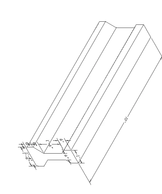
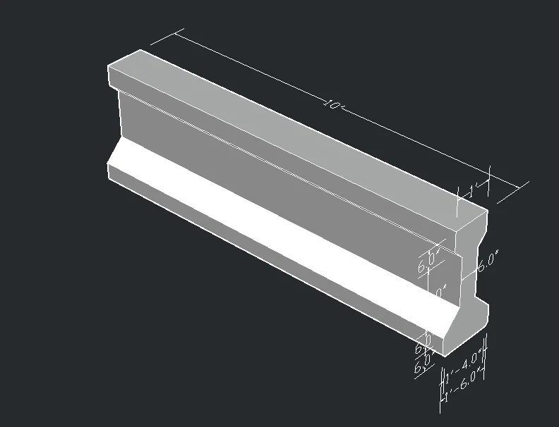
3. Create the 3D view of the AASTHO Type Girder.
AIM:
- To create a 3D model of AASTHO type girder using AutoCAD
PROCEDURE:
- Open a new AutoCAD file, set the unit as feet and inches
- Create the appropriate layers for working on it
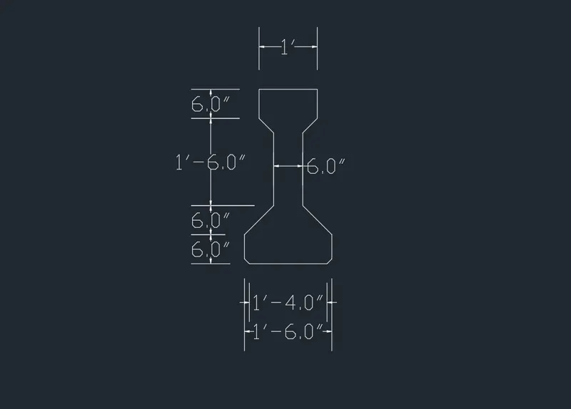
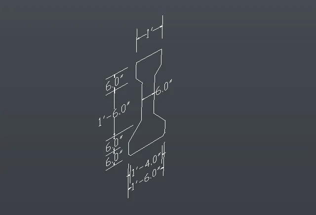
- Front view, Use the UCS command, X and Y axis in the front view plane command line to draw the I section with the given dimension. Command L draw the line 1' that is the top width of the girder
- Command L draws 6' downwards
- Give a taper distance and join the web and flange Mirror the same on the other side
- The web is given a height of 1'6" from the end of the tapering of the flange portion
- Extend the web of the offset line. Again offset 6" from the last line and taper the sides
- Draw the line of 10' in the z-direction
- Command sweep selects the section and then the path through which the section to be swept
- Give the dimension
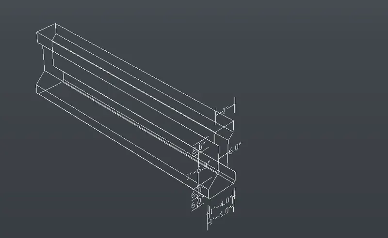
RESULT: Created the 3D model of the AASTHO girder
------------------------------------X-----------------------------------
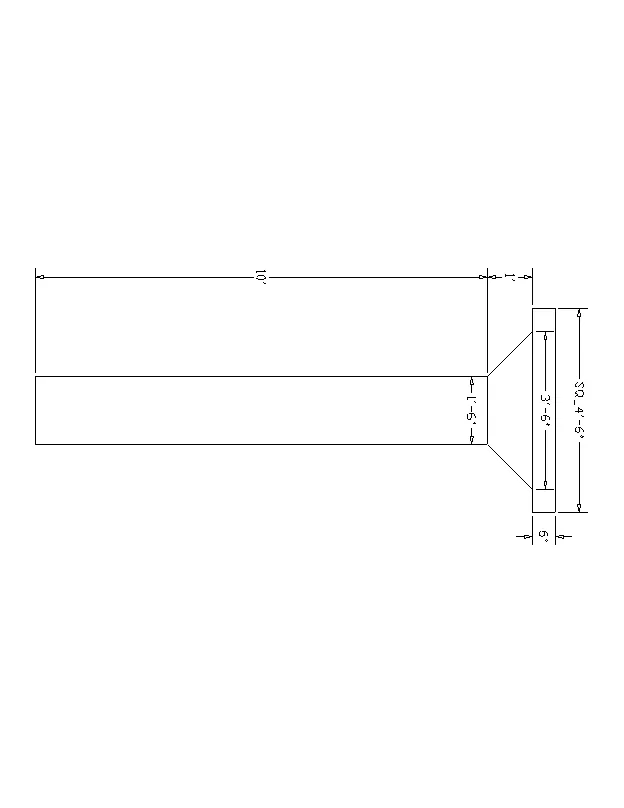
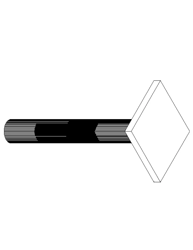
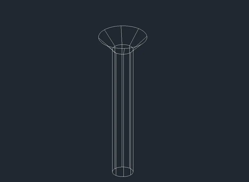
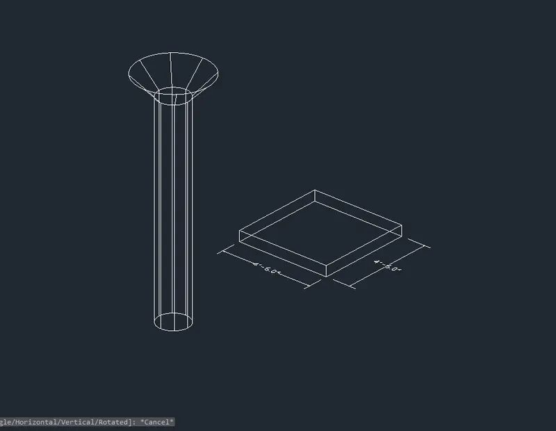
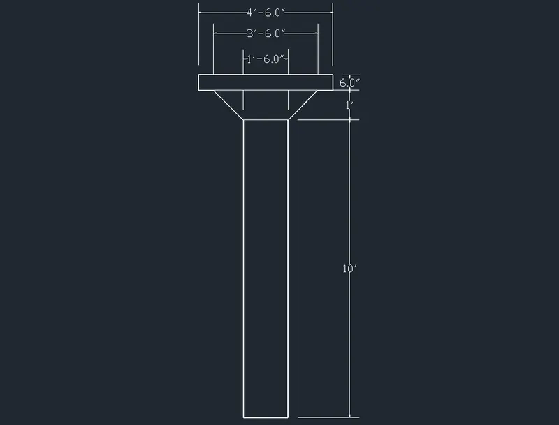
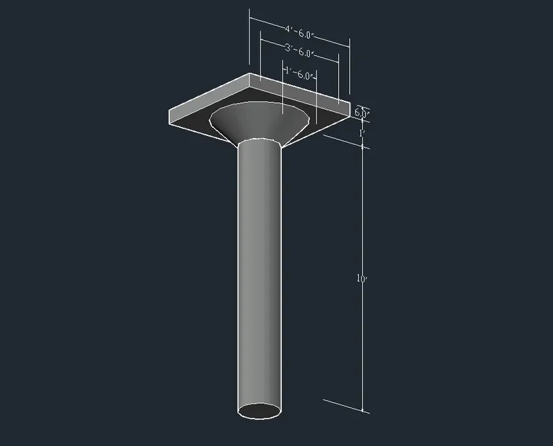
4. Create a 3d Model of a drop column with the panel as shown in the section and isometric view.
AIM:
- To create a 3D model of a drop column with a panel section and its isometric view using AutoCAD
PROCEDURE:
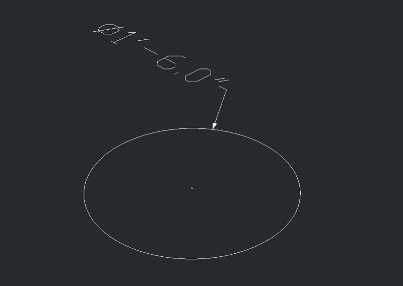
- Command circle and draw it of diameter 1'6" in the top view
- Command region and select the circle
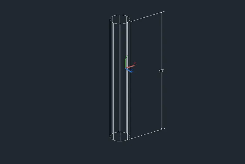
- Extrude it with a distance of 10'
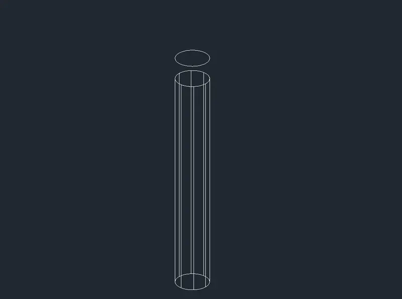
- Create a cone by clicking on a cone from the home toolbar, click the diameter, and dase diameter as 1'6"
- The Frustum of the cone is to be placed on top of the extruded circle
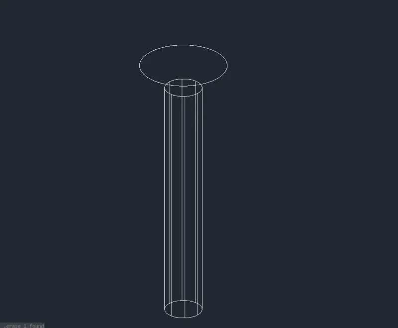
- In the top view create a rectangle of dimension 4'6" x 4'6". Extrude it to a height of 6"
- Place the rectangle at the center of the cone in the top view and also adjust in the front view
RESULT: Created the 3D model of the drop column with the panel
------------------------------------X-----------------------------------
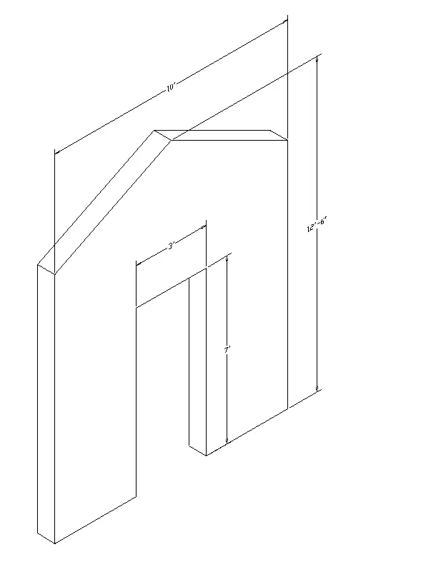
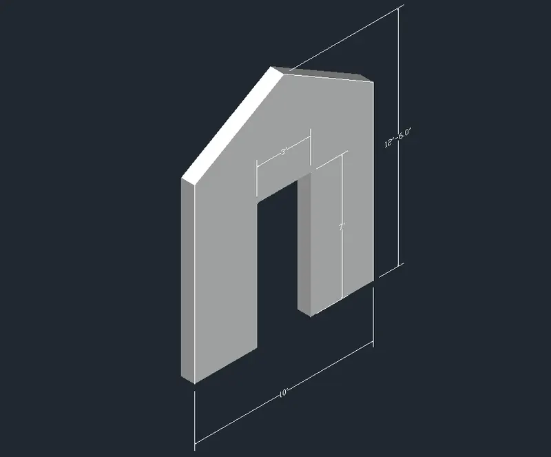
5. Create the 3d model of a wall as shown in Figure. Consider wall thickness as 9”.
AIM:
- To create a 3D model of Gable Walls using AutoCAD
PROCEDURE :
- open AutoCAD and set the units using the units command.
- use the UCS command to set the directions of the x-axis, y-axis, and z-axis.
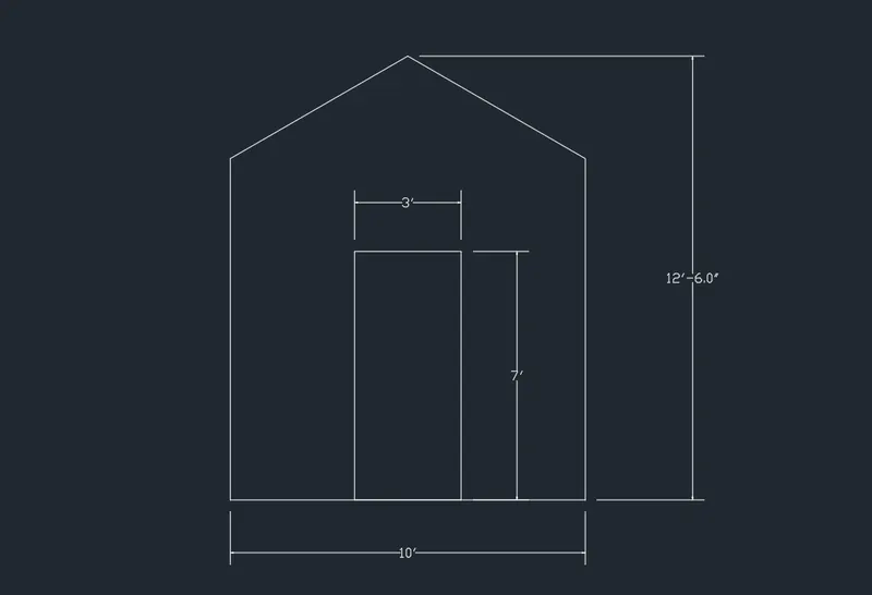
- draw horizontally forward with a length of 10'.
- draw the other line vertically upwards with a length of 10'.
- draw the line from the previous line with an angle of 125 degrees.
- Again from the previous line we draw another line with an angle of 225 degrees and with a length of 5'.
- join the line from the first line to the last line.
- draw the rectangle inside the wall as shown in the figure.
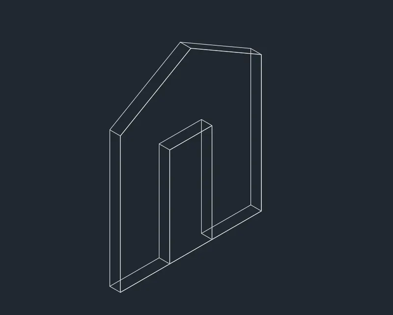
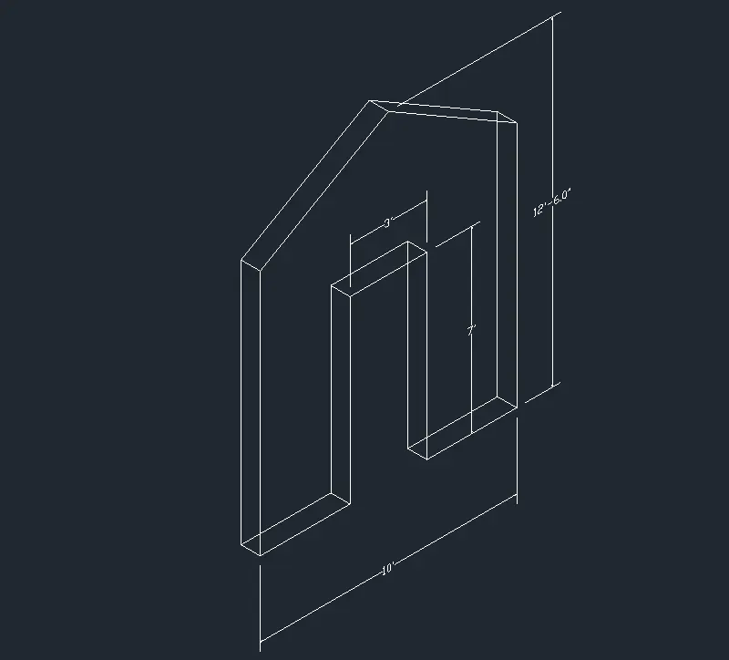
- use the extrude command to extrude the wall with a thickness of 9".
- Again we use the extrude command to extrude the inside rectangle with a thickness of 9',
- click the custom visual styles at the top left corner of the drawing screen, and select the shaded option in the custom visual styles.
- Give the dimension
RESULT: Created the 3D model of the wall
------------------------------------X-----------------------------------