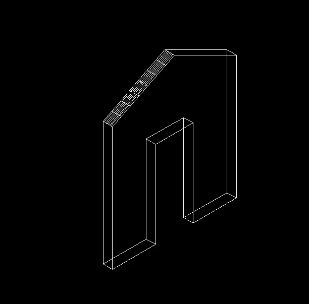
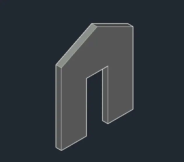
Creating various 3D Models like Furniture, Footing, Girder, Column drop with panel and Gable Wall in AutoCad
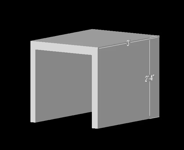
1. Create a 3D Furniture element as shown in the Figure. Assume dimensions which are missing.
Answer:
Aim: To create a 3D view of given furniture element
Commands Used: Line, Box, UCS, Rectangle, Union, Extrude, Substract, Plan, 3Dorbit, Dimlinear.
Procedure:
1. Open a new AutoCAD file, select imperial and sets the units in engineering i.e feets inches.
2. Take a box command, specify the length as 3'and width as 2'6" and give a height of 2'6".
3. Use the UCS, to draft in front face, from x and y coordinate, and say the command Plan.
4. Take a line command specify the distance of 2"
5. Take a rectangle command, specify the length as 32"and width as 2'4", now move this rectangle to the drawn 2"line.
6. Delete the line which is created as the reference, Use the command 3Dorbit to rotate.
7. Take the command extrude and extrude the rectangle in z axis.
8. Take the command Substract select the bigger rectangle then smaller one in 2D wireframe.
9. Use the command Dimlinear and specify all the distance as per the given.
Result: The 3D model of a Furniture element is created and is shown below.
AutoCAD Result:
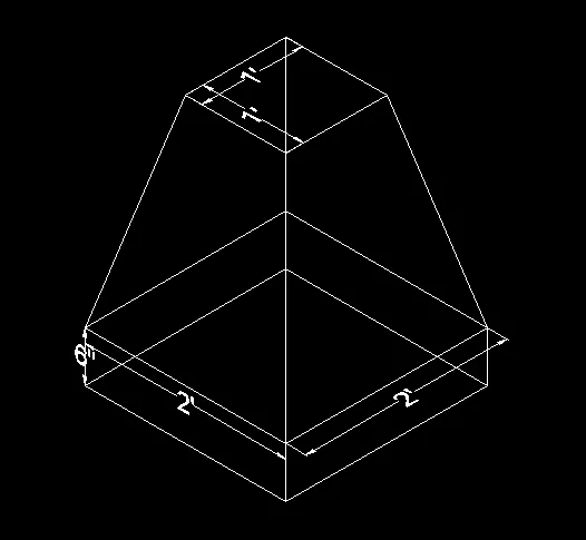
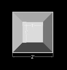
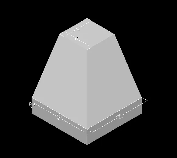
2. Create the 3d Model of an Isolated footing as shown in Figure.
Answer:
Aim: To create a 3D view of given Isolated Footing.
Commands Used: Rectangle, Extrude, Line, Dimlinear, 3Dorbot, Loft, UCS.
Procedure:
1. Take a rectangle command and create a rectangle of dimension 2'x 2' in Top View.
2. Take again rectangle command and created a smaller rectangle of 1'x1'in the same top view.
3. Use the command 3Dorbit to rotate the drawing in all the three axis direction.
4. Take the command Move and select the smaller rectangle and move it(lift it to) 2' in the z dircetion.
5. Take the command loft from command line or from the ribbon panel and select both the rectangle to loft.
6. Take the command extrude and extrude it for 6"height (Top view)
7. Use the command Dimlinear and specify all the distance as per the given.
Result: The 3D model of a Isolated footing is created and is shown below.
AutoCAD Result:
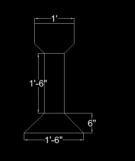
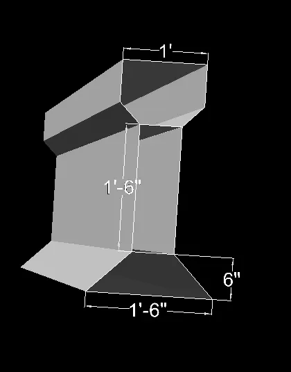
3. Create the 3D view of the AASTHO Type Girder.
Answer:
Aim: To create a 3D view of given AASTHO Type Girder.
Commands Used: Line, Offset, Mirror, Dimlinear, 3Dorbit, Sweep.
Procedure:
1. In the front view plane, Take a line command to create I section, 1' horizontal top distance of I girder.
2. Take the command offset specify the offset distance of 9" in downward direction
3. Take again offset of 3"to create 3"of two vertical lines.
4. specify the taper distance and join the wed and flange.
5. Take the command Mirror and mirror it to other side.
6. Create a wed distance of 1'6" and flange distance as 1'.
7. Draw a center line and give offset of 9"on both sides then join the tapper ends.
8. Use the command 3Dorbit to rorate the drawing, now draw a 10'line in z direction
9. Take the command sweep select the object and drag the lines.
10. Use the command Dimlinear and specify all the distance as per the given.
Result: The 3D model of a AASTHO type girder is created and is shown below.
AutoCAD Result:
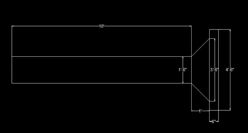
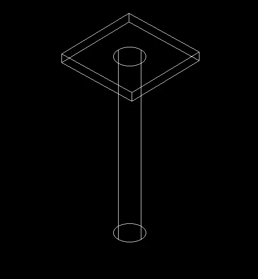
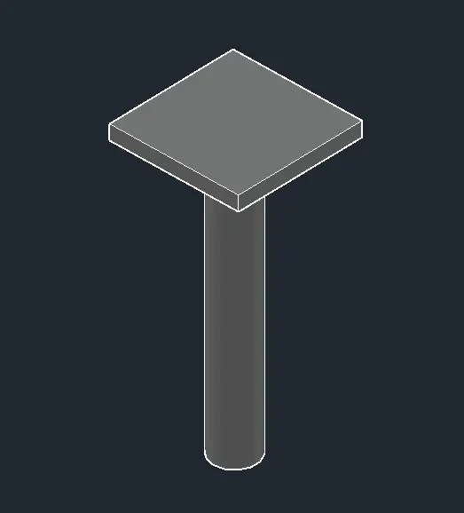
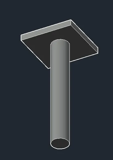
4. Create a 3d Model of a drop column with panel as shown in section and isometric view.
Answer:
Aim: To create a 3D Model of a drop column with panel in section.
Commands Used: Circle, Line, Extrude, Region, Rectangle, Cone, Dimlinaer, 3D orbit,
Procedure:
1. Take a circle command and create a circle of diameter 1'6"(Top view)
2. Select the circle, and extrude it to distance of 10'.
3. Take a cone command from the ribbon panel (Home Toolbar), from the diameter of circle, specify the base diameter as 1'6" and height of cone as 1".
4. Take a rectangle command specify the dimensions as 4'6"x4'6" (In Top View) extrude it to a height of 6".
5. In the Top view place this rectangle at the center og cone (Sanp ON)
6. Take a move command select the object and move rectangle to 10' in the bottom of the front view.
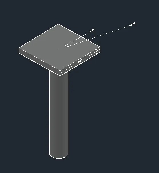
7. Use the command Dimlinear and specify all the distance as per the given.
Result: The 3D model of a drop cloumn with panel is created and is shown below.
AutoCAD Result:
5. Create the 3d model of a wall as shown in Figure. Consider wall thickness as 9”
Answer:
Aim: To create a 3D Model of a given wall.
Commands Used: , Line, Extrude, Trim, Region.
Procedure:
1. Using Relative Rectangle co-ordination system
2. Click on the SW isometric view and 2d wireframe from the view control for 3D XYZ plane
3. Take a line command, L enter and specify the first point as randomly on screen.
4. Specify the next point @3'6",0,0 enter
5. Specify the next point @0,0,7' enter
6. Specify the next point @3',0,0 enter
7. Specify the next point @0,0,-7' enter
8. Specify the next point @3'6",0,0 enter
9. Specify the next point @0,0,10' enter
10. Specify the next point @-10',0,0 enter
11. Specify the next point @0,0,-10' enter Esc
12. Now from the midpoint of top horizontal line, draw a vertical line of 2'6"to make total height as 12'6"
13. Use trim command, to erase all unwanted lines
14. Take a region command, select the object click enter Region is created.
15. Use the command, Extrude and select the object and extrude it to 9".
16. Change the view style to Shades of grey.
Result: The 3D model of a wall is created and is shown below.
AutoCAD Result: