Creating various 3D Models like Furniture, Footing, Girder, Column drop with panel and Gable Wall in AutoCad
1. Create a 3D Furniture element as shown in the Figure. Assume dimensions which are missing.
AIM:
Create a 3D furniture element as shown in the figure.
INTRODUCTION:
Create the profile by using command tools are
- Relative rectangular coordinate system
- Region
- Extrude
- 3D face
- Hide
- 3D object
Procedure:
- Open Auto cad creates new sheets with imperial units.
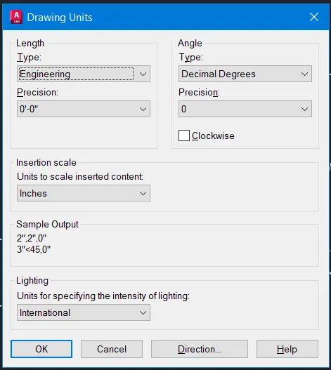
- Set the units as engineering and precision as 0'-0"
- Change the Work space to 3D modeling and set the view as SW-isometric.
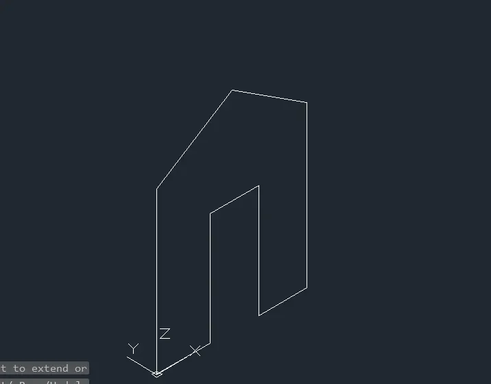
- Use PL command Specify the first point as 0,0,0
- By using relative rectangular coordinate system
- Start the point as @0,0,2'-6"
- Next point as @0, -3',0
- Next point as @0,0, -2'-6"
- Next point as @0, -2",0
- Next point as @0,0,2'-4"
- Next point as @0,2'-8"
- Next point as @0,0, -2'4"
- Close the point as @0,2",0
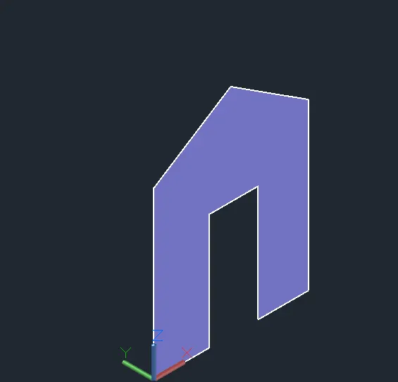
- Created drawn as shown in step by step below.
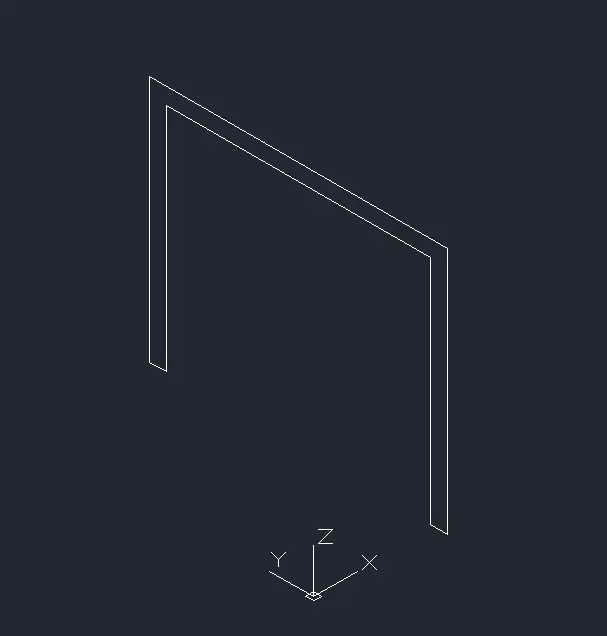
- To create the surface of the object command Region
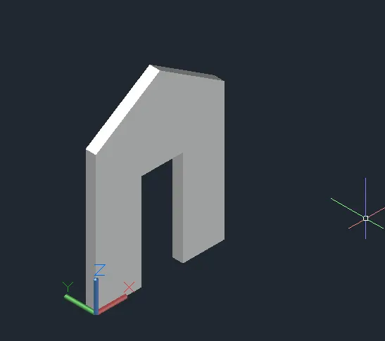
- Change the view style to Shaded
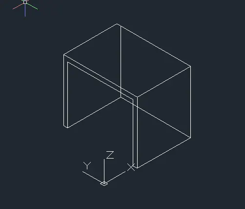
- Type Extrude the created surface in the X-axis at a distance of 2'
- Select the object to extrude the surface
- Change the view as SW isometric
- Create a rectangle dimension 2'8", 0'-2" at the base of the object created
- Make the rectangle as surface by using region
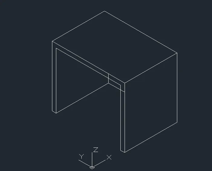
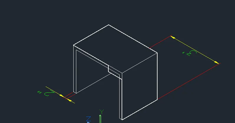
- Change the UCS style to hidden and create the DIM Following required.
RESULT:
The 3D furniture model is created as shown in figure and the missing dimension are assumed.
2. Create the 3d Model of an Isolated footing as shown in Figure.
AIM:
To create a 3Dmodel of isolated footing as shown in figure.
Introduction:
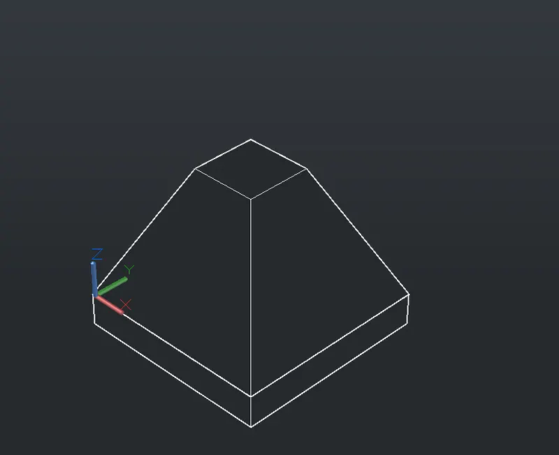
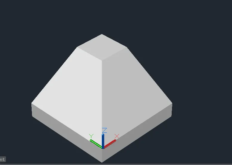
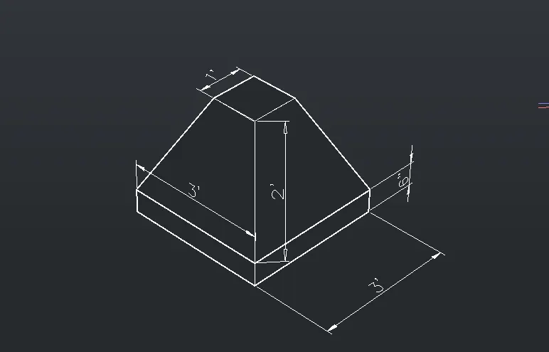
The isolated footing is created by the box and pyramid tools and dimensions it to be check Assume the size of the footing is 3'x3'
Procedure:
- Open Auto cad software and open new drawing set imperial units
- Unit as set in engineering and precision as 0'-0"
- Set the workspace to 3D modeling and set the view as Sw isometric.
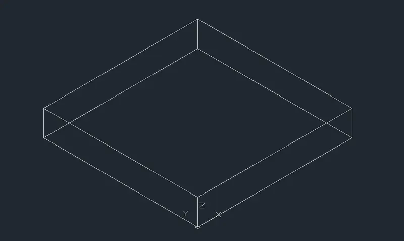
- Create a box using box tool under the solid tab
- Specify the first corner point of the box as 0,0,0
- And another corner as @3',3',0
- Specify the height as 6"
- Type UCS in the command
- Use pyramid tool create pyramid at the top level.
- Take the first point at the top first corner of the box and second point
- At the top second corner point of the box
- Select the top radius option
- Enter the top radius as 6"
- Specify the height as 2'
- Set the view style as hidden
- And create the dimensions by using Dim linear.
Result:
The 3D model of isolated footing is created as shown in the figure.
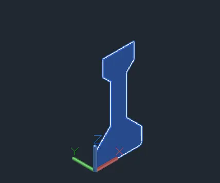
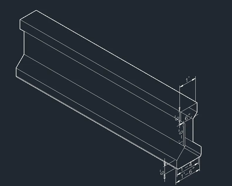
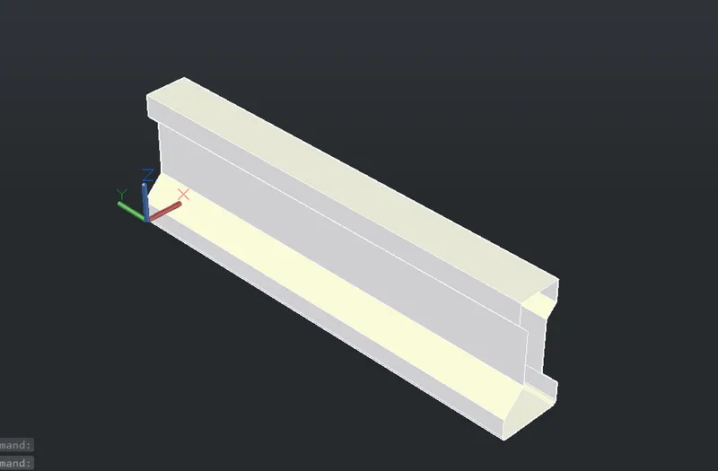
3. Create a 3D view of the AASTHO Type Girder.
AIM:
Create a 3D view of the AASTHO Type girder.
Procedure:
- Create a new sheet
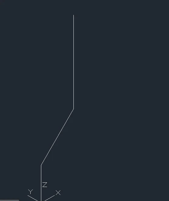
- Set the units as 0'-0"as engineering
- Select the object or bound area
- Specify the extrusion height or multiple 4 sides
- Click a face, curve, inside bounded area
- Regenerating model and press esc
- With the line draw a 6" downwards.
- With snap on draw a line from the center of 1' and offset 3" on both sides such that the width of web becomes 6"
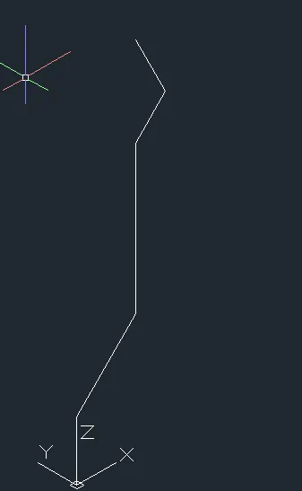
- Create a tapper distance and join the web and the flange mirror the same on the other side
- Extend the web to the offset line again offset 6 from the last line and taper the sides mirror the tapered portion
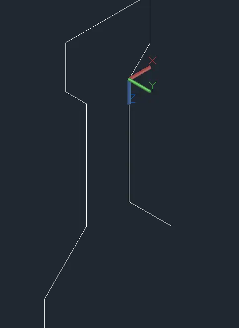
- The sides should be tapered such that the bottom should be a center line and offset 9"
- Join the tapper
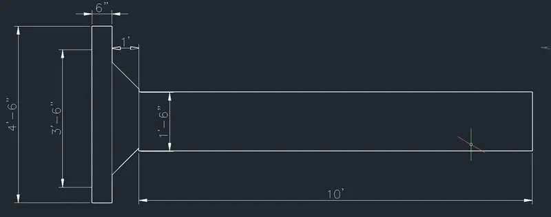
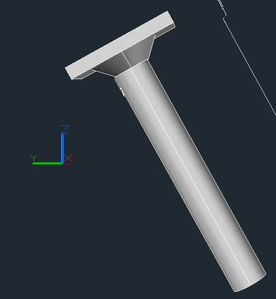
4. Create a 3d Model of a drop column with panel as shown in section and isometric view.
AIM:
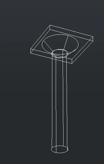
To create a 3D model of a drop column with panel using AutoCAD software.
INTRODUCTION:
- Commands are used in New
- Box
- Union
- Cone
- Cylinder
- Hide
- 3D face
- Region
- RO
- Move
- Dim linear
PROCEDURE:
- Type Q new in command, press enter
- Select the imperial as default setting and select ok
- Type UN in command box, set the units engineering with the precision as 0'-0"
- Set the limits and LIMAX as 20',20'
- Enter z and type a for zoom all
- From view Tab Keep on the view cube icon from the ribbon
- Set the UCS icon set to default
- Type BOX in command and enter
- Specify the first corner point select the length option from the ribbon tab
- Specify the length as 4'-6" press enter
- Specify width as 4'-6" press enter
- Specify the height as 6" press enter
- Command REC and set center point mention dimensions are length as 3'-6" width as 3'-6"
- Type move and select the rectangle at basepoint
- Specify the point as @6",6"
- Click PYRAMID and select the option Edge
- Select the First Point of edge as rectangle and second point
- Select the TOP radius as 1'-6" and the height as 1'
- Click on the ribbon tab CYLINDER. Select the 3P
- Select the first, second and third point as midpoint of top pyramid and height as 10'
- Type HIDE and select the object
- Change the view to front
- Command REG select the object and press enter
- Finally Type DIMLIN and give the dimensions
Result:
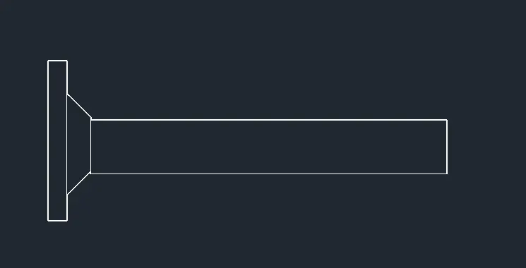
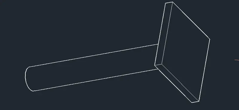
3D model of a drop column with panel is created in AutoCAD using above mentioned procedure as shown below:
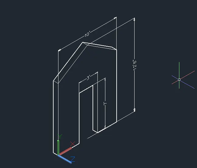
- Create the 3d model of a wall as shown in Figure. Consider wall thickness as 9”.
AIM:
To create a 3D model of a wall using AutoCAD Consider wall thickness as 9"
INTRODUTION:
Commands are uses:
- Q NEW
- Unit
- LIMAX
- Zoom
- 3P
- MIR
- Region
- Extrude
- DIM Linear
PROCEDURE:
- Type Q new in command, press enter
- Select the imperial as default setting and select ok
- Type UN in command box, set the units engineering with the precision as 0'-0"
- Set the limits and LIMAX as 20',20
- 'Enter z and type A for zoom all
- From view Tab Keep on the view cube icon from the ribbon
- Set the UCS icon set to default
- Type 3P in command and press enter
- Specify next point as @-5', -2'6"
- Specify next point as @4'2",0
- Specify next point as @0,7'
- Specify the next point as @0,18"
- Type MIR and enter
- Select the entire drawing Select the first point on mirror line
- Polyline and specify second point on mirror line as other endpoint of polyline and mirror the line
- Command REGION Select the entire by using the crossing window
- Command Extrude select the object at the height as @0,0, -9" and enter
- Type Dim Linear and give the dimensions
- Change the custom visual style from 2D wireframe to HIDDEN to desired view
Result:
3D model of a wall is created in AutoCAD software by following the above-mentioned procedure as shown below