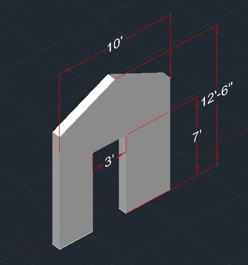
Creating various 3D Models like Furniture, Footing, Girder, Column drop with panel and Gable Wall in AutoCad
1.AIM:
⦁ To create a 3D Furniture elements using the various commands in AutoCAD.
PROCEDURE:
⦁ Set the units as engineering and inches.
⦁ Set the limits.
⦁ Go to the settings and change the view of the page from drafting to 3D modelling.
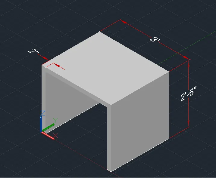
⦁ First take the top view of the page and draw a rectangle with the dimension of 2'-6"x3'-0".
⦁ and then we take a 3D view port in the current view port.
⦁ Type the 3D orbit to view a 3D view port.
⦁ Then we take the all box dimensions to create it from the origin point.
⦁ Next point we take to X direction of (@2'-6",0,0)
⦁ Type extrude to create the surface.
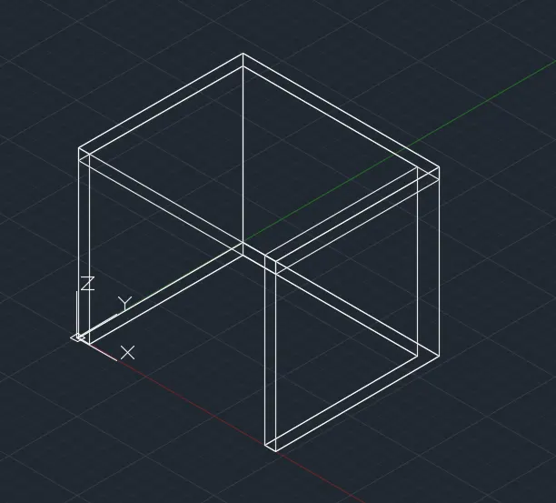
⦁ Then we have to change the view of 2D wire, shaded, conceptional etc.
⦁ Type 3D face for allows to generate 3D faces by identifying.
RESULT:
⦁ The diagram of 3D furniture elements is drawn as per the dimensions using the autocad.
2. AIM:
⦁ To create a 3D model of an isolated footing using the various commands in Autocad.
PROCEDURE:
⦁ Set the units as engineering and inches.
⦁ Set the limits.
⦁ Go to the settings and change the view of the page from drafting to 3D modelling.
⦁ First take the top view of the page and draw a rectangle with the dimension of 4'-0"x4'-0".
⦁ And then we take the 3D custom view.
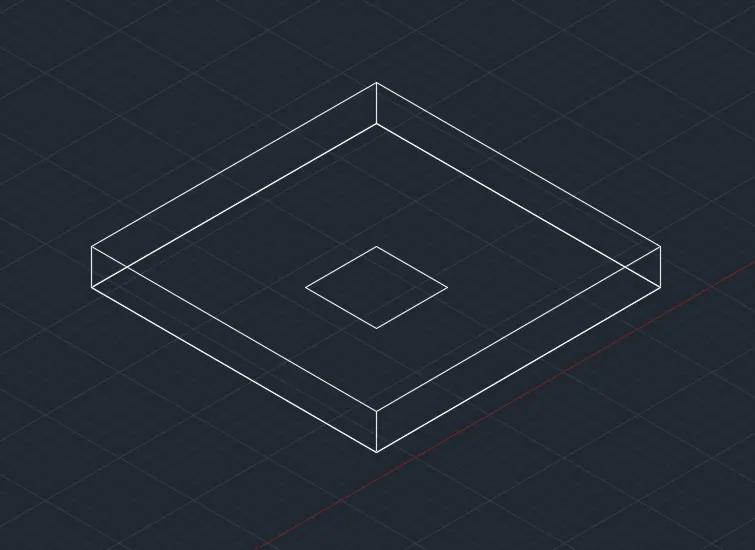
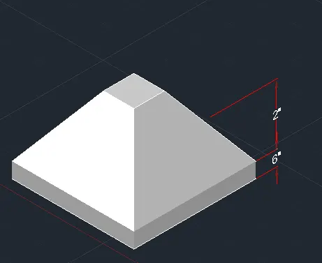
⦁ The footing dimension is 4'x4'.
⦁ The depth of footing is 6" and reduced to the depth of 2" and the width is 1'.
⦁ join all the lines.
⦁ Type the 3D orbit to view a 3D view port.
⦁ Type 3D face for allows to generate 3D faces by identifying.
RESULT:
⦁ The diagram of 3D model of an isolated footing is drawn as per the dimensions using the autocad.
3. AIM:
⦁ To create the 3D view of the AASTHO type girder using the various commands in autocad.
PROCEDURE:
⦁ Set the units as engineering and inches.
⦁ Set the limits.
⦁ Go to the settings and change the view of the page from drafting to 3D modelling.
⦁ First take the top view of the page .
⦁ Draw the girder using the line command specify the origin point 0,0,0.
⦁ Specify the next point is (@1'-6",0,0)
⦁ Specify the next point is (@0,0,6")
⦁ Specify the next point is (@6"<0<135) and to follow the all given dimensions to draw the section.
⦁ Type the 3D orbit to view a 3D view port.
⦁ Type 3D face for allows to generate 3D faces by identifying.
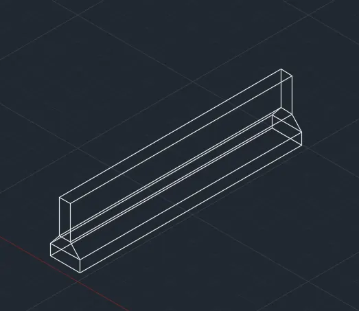
⦁ Type Region to convert objects that encloses an area into a 2D region objects.
⦁ Type extrude to create the surface.
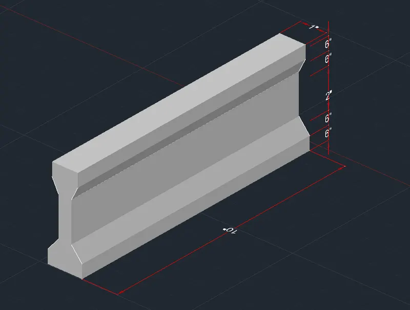
⦁ The extrude length of the section girder is 10'.
⦁ Then we have to change the view of 2D wire, shaded, conceptional etc.
RESULT:
⦁ The diagram of 3D type of AASTHO girder type is drawn as per dimensions using the autocad.
4. AIM:
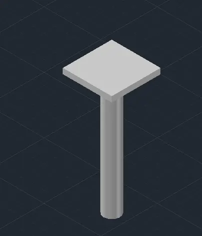
⦁ To create a 3D model of a drop column with panel using the various commands in autocad.
PROCEDURE:
⦁ Set the units as engineering and inches.
⦁ Set the limits.
⦁ Go to the settings and change the view of the page from drafting to 3D modelling.
⦁ First take the top view of the page .
⦁ Type rectangle to create a rectangle with a given dimensions.
⦁ and we take a 3D custom view
⦁ the rectangular size is 4'-6".
⦁ type C to create the circle and the column cap height is 1'.
⦁ the height of the column is 10'.
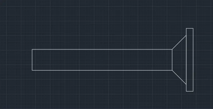
⦁ Type Region to convert objects that encloses an area into a 2D region objects.
⦁ Type extrude to create the surface
⦁ Type the 3D face for allows to generate 3D faces by identifying.
RESULT:
⦁ The diagram of 3D model of a column with drop panel is drawn by using the autocad.
5. AIM:
⦁ To create a 3D model of the wall using the various commands in autocad.
PROCEDURE:
⦁ Set the units as engineering and inches.
⦁ Set the limits.
⦁ Go to the settings and change the view of the page from drafting to 3D modelling.
⦁ First take the top view of the page .
⦁ Before we start the 3D work to create a plan of wall at 2D.
⦁ To make the wall thickness of 9"
⦁ create the door with the dimension of 3'-0"x7'-0" with the line command.
⦁ Type the region to convert objects that encloses an area into a 2D region objects.
⦁ type the extrude to create a surface or solid of a 2D surface or a 3D curve.
⦁ Type the 3D orbit to view a 3D view port.
⦁ Type 3D face for allows to generate 3D faces by identifying.
⦁ type region to convert the objects that enlcoses.
⦁ type the subtract to remove the open required places.
RESULT:
⦁ The diagram of 3D model of a wall is drawn by using the autocad.