Creating various 3D Models like Furniture, Footing, Girder, Column drop with panel and Gable Wall in AutoCad
C1:
Aim and introduction:To Create a 3D Furniture element
Procedure:
Steps:
- Using a line command draft the elements.
- Using REGION command make a single object of the element
- Extrude is used for the extrusion
- Subtract the unnecessary object using substract command.
- View the objects in 2d wireframe,Conceptual,Hidden and Realistic.

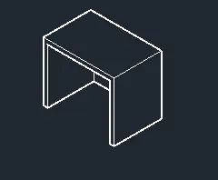
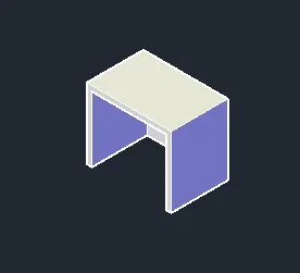
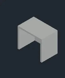
Results: Creation of a 3D Furniture element using autocad 3d modelling.
C2:
Aim and introduction:To Create the 3d Model of an Isolated footing
Procedure:
Steps:
- Using a line command draft the elements.
- Using REGION command make a single object of the element
- Move command is used for the moving of objects.
- Extrude is used for the extrusion
- 3DFACE is also used
- View the objects in 2d wireframe,Conceptual,Hidden and Realistic.

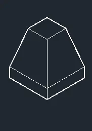
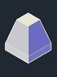
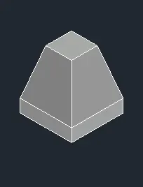
Results:
Creation of the 3d Model of an Isolated footing using autocad 3d modelling.
C3:
Aim and introduction:To Create the 3D view of the AASTHO Type Girder.
Procedure:
Steps:
- Using a line command draft the elements.
- Using REGION command make a single object of the element
- Move command is used for the moving of objects.
- Extrude is used for the extrusion
- 3DFACE is also used
- View the objects in 2d wireframe,Conceptual,Hidden and Realistic.
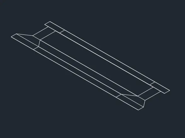
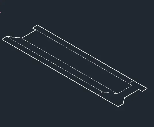
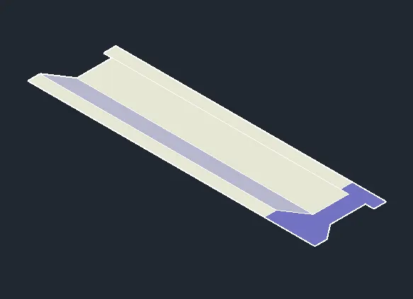
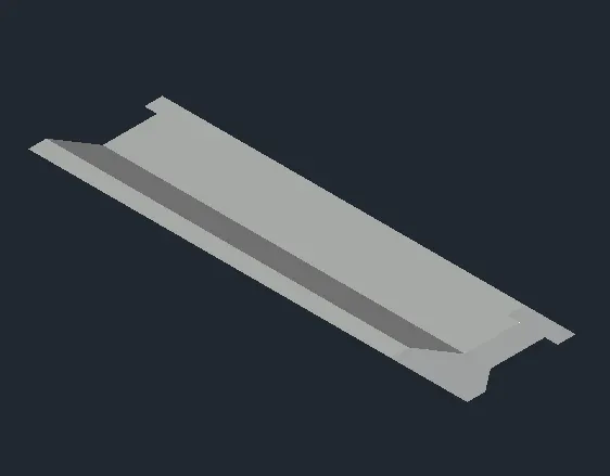
Results:
Creation of the 3D view of the AASTHO Type Girder using autocad 3d modelling.
C4:
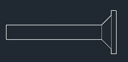
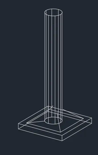
Aim and introduction:To Create a 3d Model of a drop column with panel section and isometric view.
Procedure:
Steps:
- Using a line command draft the elements.
- Using REGION command make a single object of the element
- Move command is used for the moving of objects.
- Extrude is used for the extrusion
- 3DFACE is also used
- View the objects in 2d wireframe,Conceptual,Hidden and Realistic.
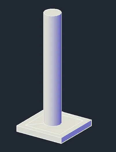
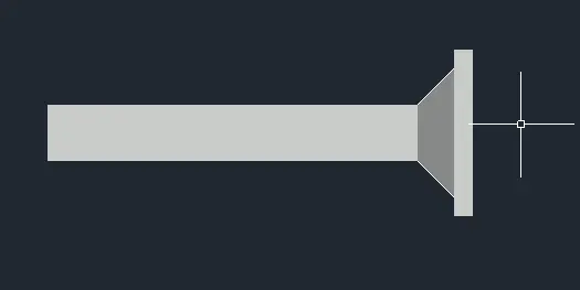
Results:
Creation of a 3d Model of a drop column with panel section and isometric view using autocad 3d modelling.
C5:
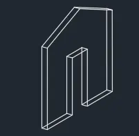
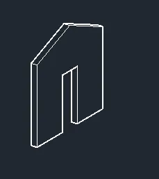
Aim and introduction:To Create the 3d model of a wall as shown in Figure. Consider wall thickness as 9”.
Procedure:
Steps:
- Using a line command draft the elements.
- Using REGION command make a single object of the element
- Extrude is used for the extrusion
- View the objects in 2d wireframe,Conceptual,Hidden and Realistic.
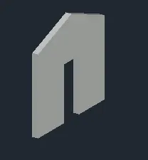

Results:
Creation of the 3d model of a wall as shown in Figure. Consider wall thickness as 9” using autocad 3d modelling.