Creating a Floor plan, Footing detail and Isometric view using AutoCad
C1:
Aim and introduction : To create C/S of load bearing wall over spread footing
Procedure:
Steps:
- using RECTANGLE command construct a rectangle
- Polyline is used for further construction by using command PLINE
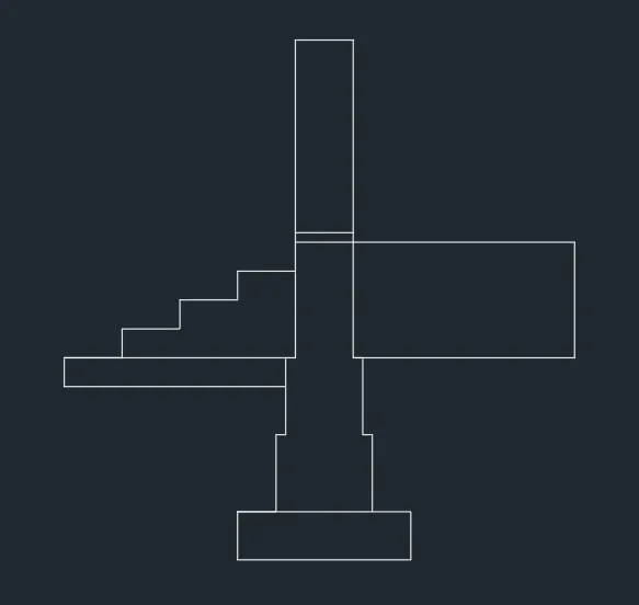
Results: Creation of C/S of load bearing wall over spread footing using rectangle and polyline tool.
C2:
Aim and introduction:To create C/S of Isolated footing
Procedure:Using line,polyline,chamfer and offset created
commands used are LINE,PLINE,CHAMFER,OFFSET
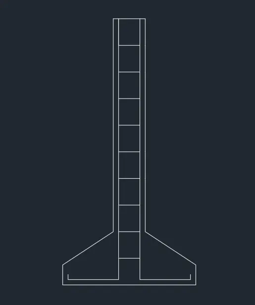
Results:Creation of C/S of Isolated footing using polyline and offset tool
C3:
Aim and introduction:To create Line diagram of a two bedroom building
Procedure:Using line and offsets it is created
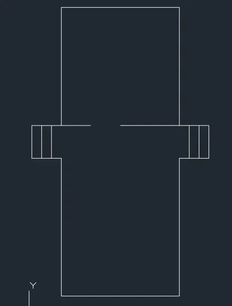
Results: Creation of Line diagram of a two bedroom building
C4:
Aim and introduction:To create C/S of load bearing wall showing foundation details
Procedure:Using line and polyline command it is constructed
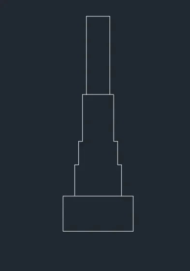
Results:Creation of C/S of load bearing wall showing foundation details
C5:
Aim and introduction:To create the Isometric view of steps
Procedure:Steps are created using Isometric top and right
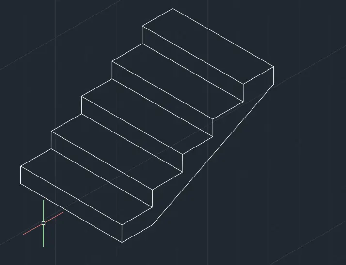
Results:Creation of Steps using Isometric top and right
C6:
Aim and introduction:To create Isometric view of gable wall
Procedure:Using isometric commands Gable wall is constructed
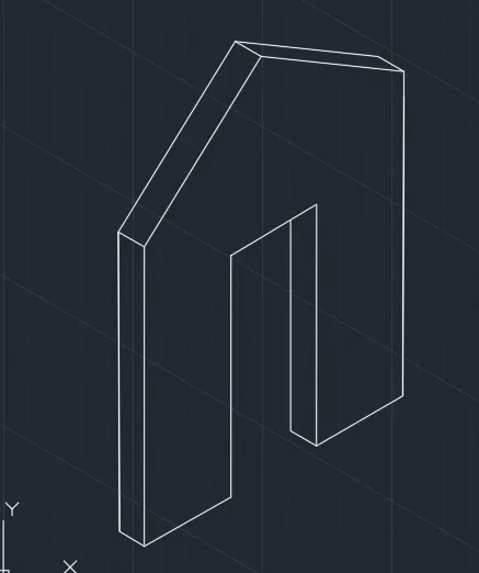
Results:Creation of Isometric view of gable wall