Creating various 3D Models like Furniture, Footing, Girder, Column drop with panel and Gable Wall in AutoCad
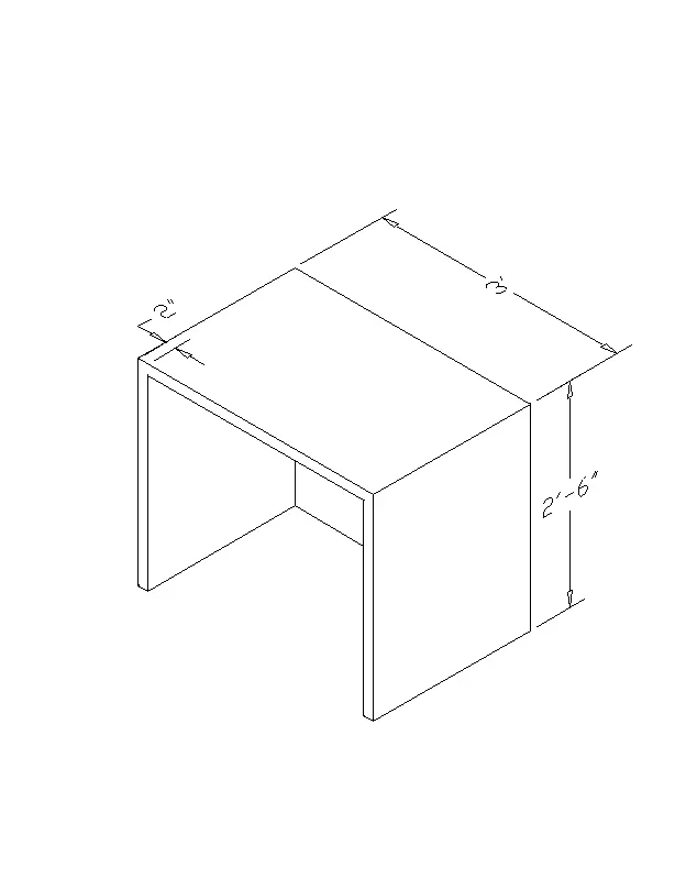
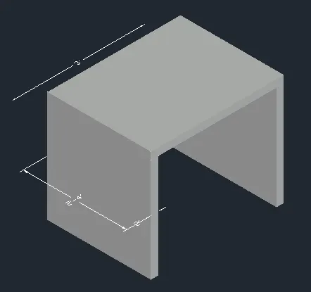
1. Create a 3D Furniture element as shown in the Figure. Assume dimensions which are missing.
Procedure :
- Creat the autocad and having the units and given the limits for the file
- And at the top view Pick a box from the ribbon tool box and give the length and width of it 3'-0"x 2'6" .
- and also specfic the height of the 2'-6" . and give the extuded command and give the 2" for the rectangle .
- And trim the remaining Unwanted lines using the 3dorbit using for it .
- And extruded the rectangle giving the 2'-4" for it .
- And Using the ucs command give the dimension for it using the dimlinear of it.
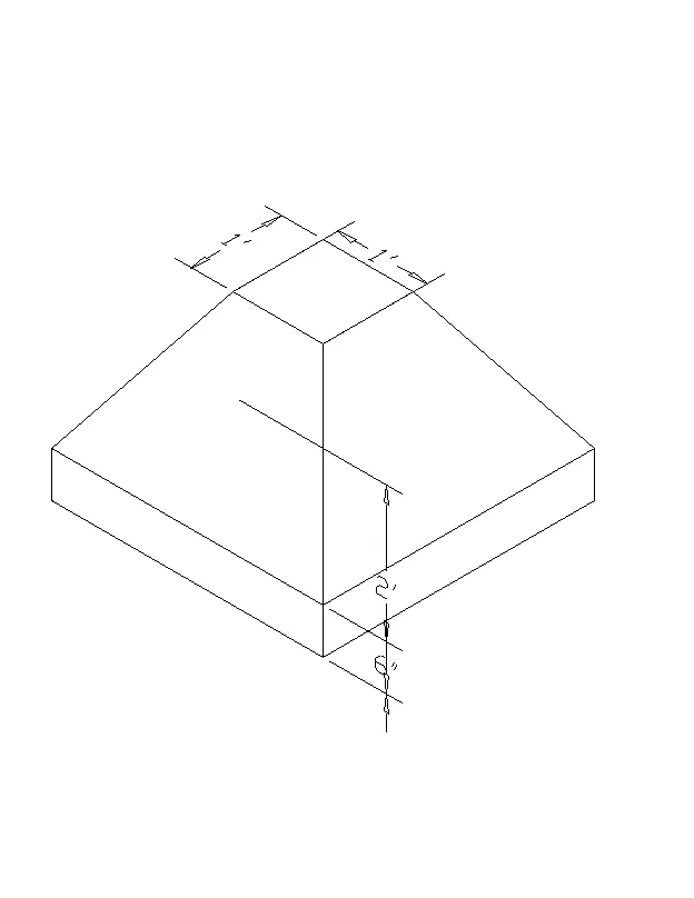
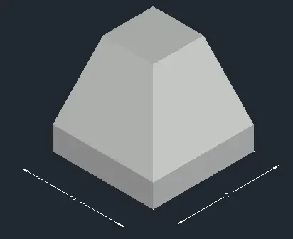
2. Create the 3d Model of an Isolated footing as shown in Figure.
Procedure :
- Draw the rectangle using the box command give the length and width of the 2'x2'
- Using the 3dorbit command is use to see the use the suitable one .
- And draw the other rectangle of giving the the length and width of 1'x1'
- and again given the height of the 2' for it . towards the z-axis
- And Click on the loft from the toolbar and select the two rectangle for the loft.
- And Again draw the other rectangle and given the extrude the height of 6" and place the both of it and and make the union for it using in tool for the ribbon toolbar.
3. Create the 3D view of the AASTHO Type Girder.
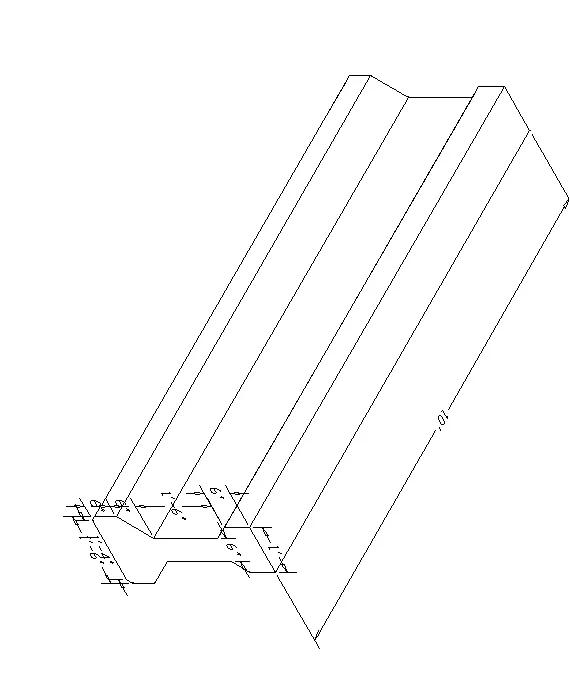
Procedure:
- Using the ucs command and make the x and y axis for the fornt viewplan
- And using the line command Draw the line of 1' and and given the 6" height and draw the midline of the height of 9"
- And give the offset of 3" on the both sides and mirror command on the other side
- And Give the height of the height of 1'6" , offset distance And also on the other side for it .
- And the trim the remaing the lines for it and other side give the offset of it .
- And given the length of the line of 6" on the other side of it .
- and draw the horizontal line length of 1'-4" from the center drawline offset 8" on the both side .
- And extended the line on the for it .
- And using the Boundary command pick the inner area of it join it and region for it using the region command .
- trun the 3d orbit and view and draw the of 10' in z direction . And Give the sweep command using the in the toolbar and path througth using the sweep command .
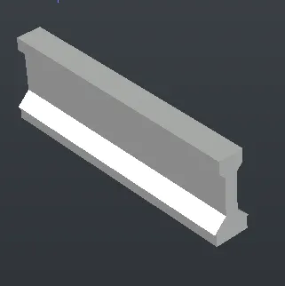
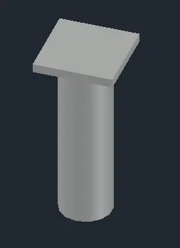
4. Create a 3d Model of a drop column with panel as shown in section and isometric view.
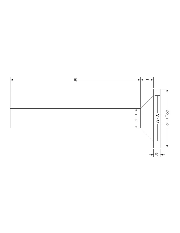
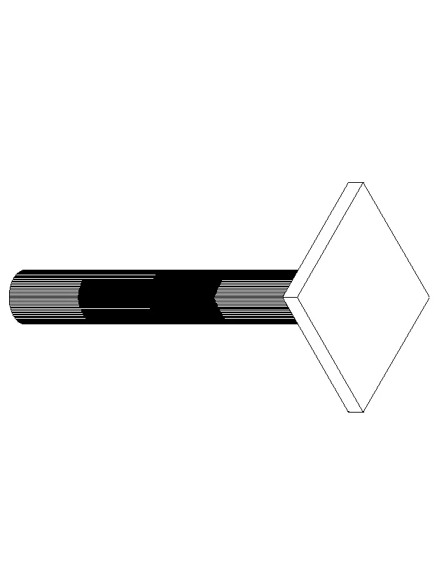
Procedure :
- Create a circle of diameter 1'-6" on the top view . Extrude command from the ribbon toolbar abd given the distance of 10'.
- Create a cone taken from the home toolbar . and Give the base diameter as 1'-6 and height of a cone as 1".
- And Place the cone on the top of the cylinder of it at the center of column .
- And Rectangle of dimension of 4'-6"x 4'-6" and extrude of it height of 6"
- And Place the rectangle at the center of a cone and adjus the front view .
- Place the both cone and rectangle above the cylinder at the height of 10'.
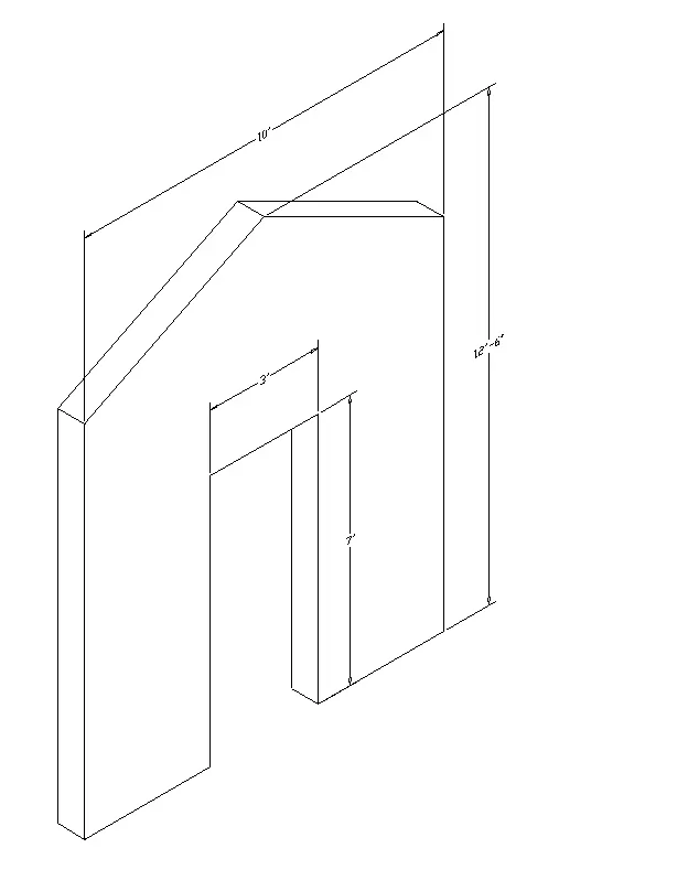
5. Create the 3d model of a wall as shown in Figure. Consider wall thickness as 9”.
Procedure :
- Draw a rectangle of 10'x 9" . And create the line at the mid of and give the off set 1.5" on the both side it is open of the door.
- Using the boundary and creat the region for the both side of the wall .
- Extrude the regon to height of 12'-6" height.
- And Draw the rectangle at the place opening door and move up to the height of 7' from the bottom .
- Draw the line from the center of the moved line door . Draw slanting line from the total height from the center line intersecting the edge .
- Mirror the line towards the horizontal line an d join .
- Draw slanting linee from the total height from the center intersecting the edge .
- Trim off the remaing lines and center line join the triangle with join command .
- Using the region command created the region for the triangle .
- Give the extruded rectangle and with the help of grid bring it down to the level of the triangle base on bothsides . Extrude the rectangle of door to a height equal to base of triangle .
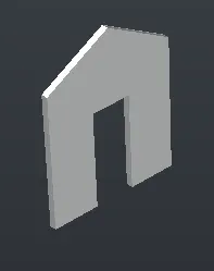
Results :