Creating various 3D Models like Furniture, Footing, Girder, Column drop with panel and Gable Wall in AutoCad
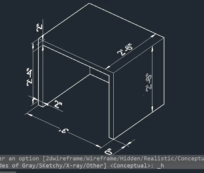
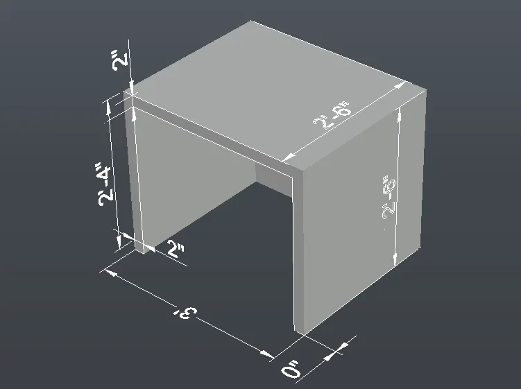
1. AIM: TO CREATE 3D MODEL OF FURNITURE
INTRODUCTION: The process of creating any surface of an object in three dimensions by using tools in autocad is called 3D modeling.
- wireframe modeling
- surface modeling
- solid modeling
COMMANSD USED-
- rectangle tool
- extrude
- subtract
- UCS
- box
- offset
- move
- sweep
- cone
- region
- boundry
PROCEDURE:
- open autocad 2021 file.
- set the unit as impherical.
- units-set to engineering with precision 0'0"
- set the limax as 100,100.
- zoom command-all,set the page.
- from setting switch to 3D modelling.
- set to top view- 2D wireframe.
- draw a rectangle of dimension 3'x3' in xy plane.
- explode the rectangle
- offset three sides at distance 2".
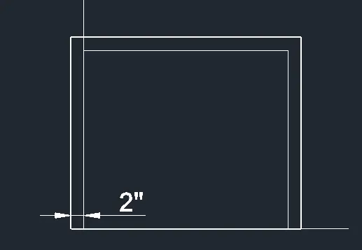
- enter boundary command and select offset lines,make a region.
- similalry repeat the same for other two sides and whole rectangle.
- go to default view by clicking on home icon.
- select extrude from ribbon and select all region.
- extrude at the height in z-axis 2'6".
- select subtract command,select the rectangle-enter.
- select smaller rectangle-enter.
- select union command and select all object-enter.
- use linear dimension and measure by switching UCS.
RESULT:
2. AIM:Create the 3d Model of an Isolated footing
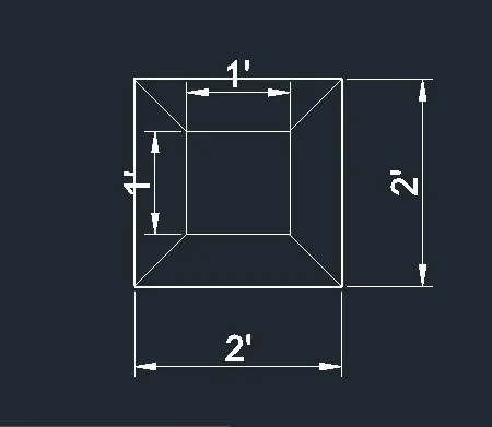
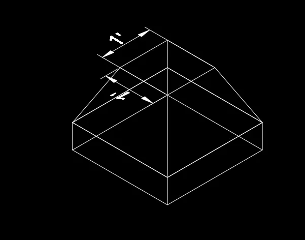
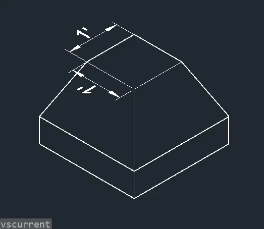
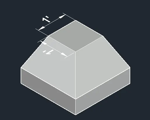
INTRODUCTION: given footing is an isolated footimg/tappering footing of diemsnions 1'x1' at the top and 2'x2' at bottom with 6" pcc bed.
command used here is tappering option in box command .
PROCEDURE:
- set the view to top and 2d wireframe.
- draw a recatngle of each side 2".
- select offset command ,select recatngle and enter the distance as 1'.
- move to default view.
- enter move command,select 1'x1' rectangle and move at a distance of 3'.
- select loft command,select two rectangle and enter.
- now extrude the rectangle of size 2'x2' with height 6".
RESULT:
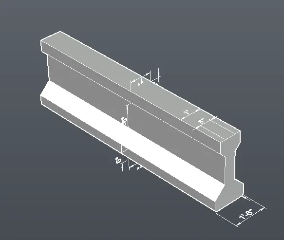
3. AIM:Create the 3D view of the AASTHO Type Girder.
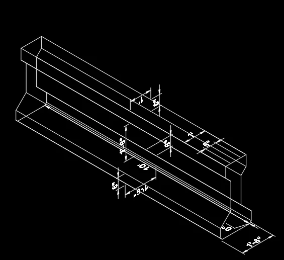
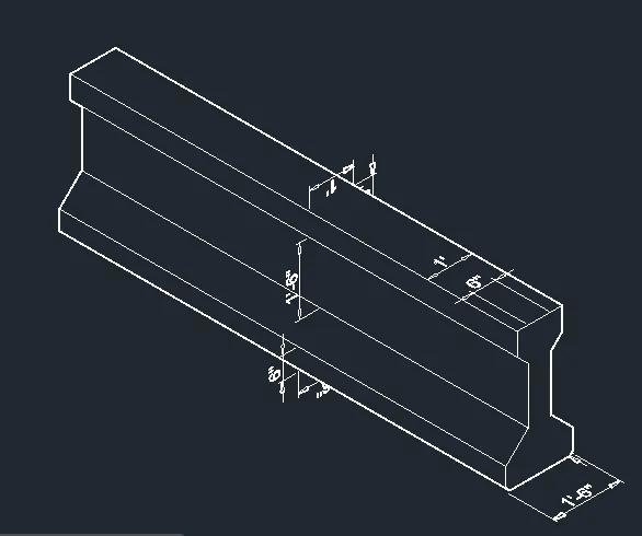
INTRODUCTION: aastho are type of grider,which has expanded the width of upper and lower flange.
these types are mainly used in bridge construction.
PROCEDURE:
- set the view to top and wireframe.
- draw a set of rectangle od dimension 10'x6",10'X1'4",10'x1'6" and 10'x1'.
- now allign the rectangle in bigger recta
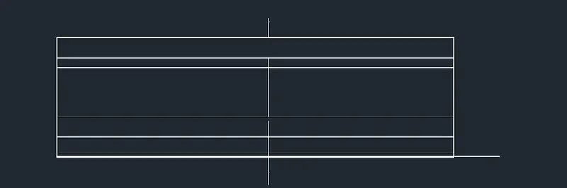 ngle using geometric center.
- set the view to SW isometric.
- extrude recatngle upto given heights,for example for 10'x6" extrude upto height 1'6".
- follow the same of remaining.
- allign the recatngle upto certain height usig move command,example move rectangle 10'x6" at height 0,0,1'.
- now tamper last second rectangle by selecting width face,specifying base point and axis,enter angle as -15.
- similary for 2nd recatngle, neter angle as -45.
- use union command to join the extruded section.
RESULT:
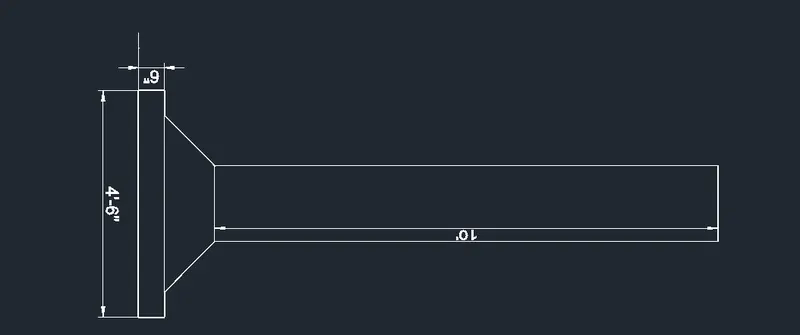
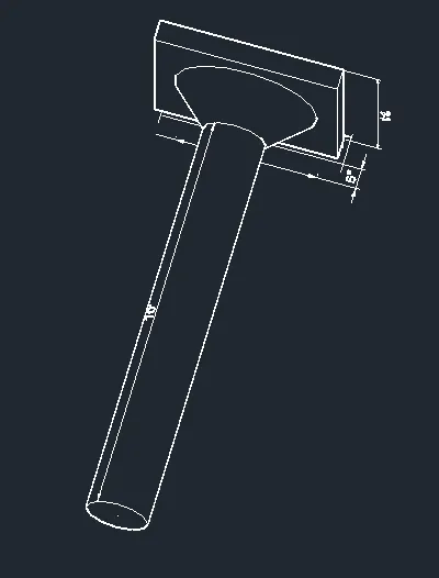
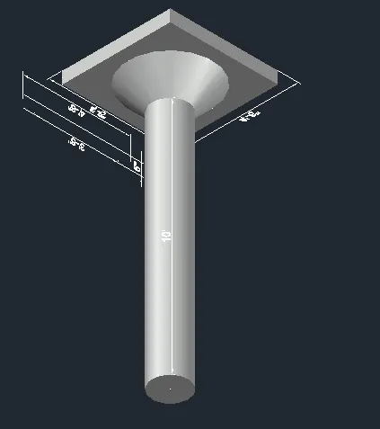
4. AIM:Create a 3d Model of a drop column with panel
INTRODUCTION: Drop panels are the rectangular portion provided above the column and below the slab in order to restrict slab from getting sheared and undergo rupture.
PROCEDURE:
- select the top view with wireframe.
- draw a circle of diameter1'6".
- extrude the circle at height 10' in default view.
- move back to top view and,draw a recatgle of sides 3'6".
- place the rectangle on circle using onsnap or enter distance as 0,0,10.
- extrud ethe recatngle at height of 1'.
- select tamfer command from solidedit tool and select the face .
- sepcify the base point ad enter agle as 45 degree.
- repeat the same on other side or use loop/chain command in tamper.
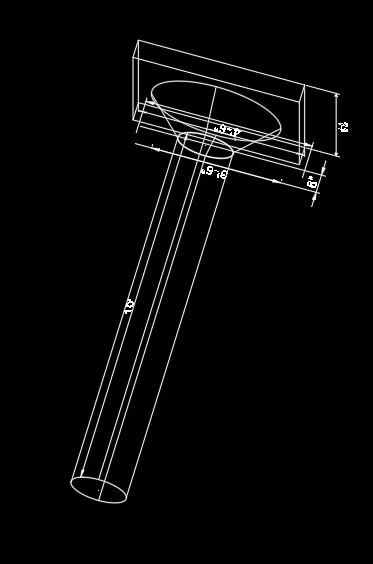
- back to top view and draw a rectangle of side 4'6".
- move back to isometric view and extrude at height 6".
- place the recatngle on top of 3'6" rectangle using UCS icon or distance command.
- use union to make object one.
RESULT:
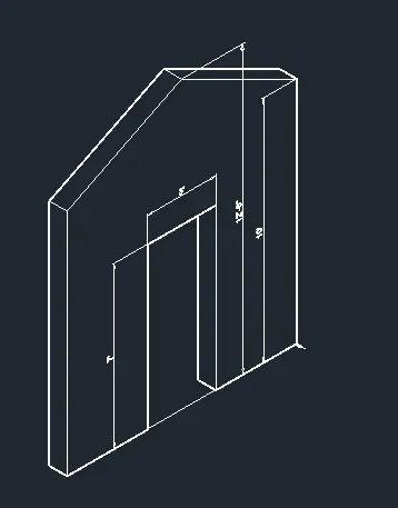
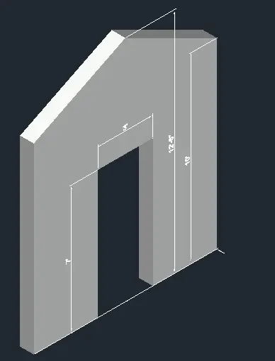
5.AIM:Create the 3d model of a wall
PROCEDURE:- set the top view and wireframe.
- draw a rectangle of dimension 10'x9"
- noW explode the rectangle.
- offset the width on both side at distance of 3.5'.
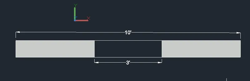
- enter boundry command-select the point-convert to region.
- set the view to default isometric.
- extrude the corner region upto height 12'6".
- now move the door rectangle to heigt 0,0,7'.
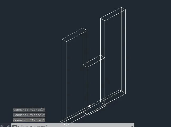
- now extrude the moved rectangle upto 12.5'.
- set the view to front and draw a triagnle of sides 5.5' and base 10'.
- make traignle as region using boundry command.
- ectrude the traignle at distace 9" towards y axis.
- use preepull or grip to reduce the recatngle wall.
- use union command to join all extruded walls.
RESULT: 3d model of wall is drawn