Creating various 3D Models like Furniture, Footing, Girder, Column drop with panel and Gable Wall in AutoCad
CREATING VARIOUS 3D MODELS IN AUTOCAD.
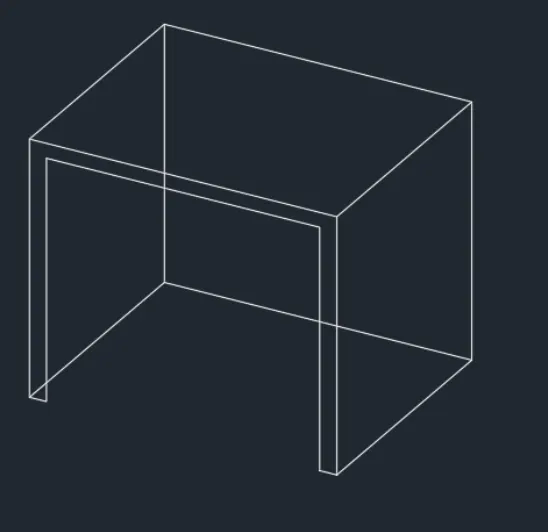
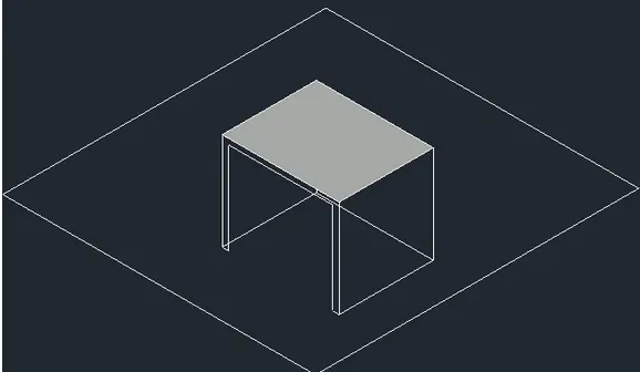
1.AIM: Create a 3D model of furniture element in Autocad.
PROCEDURE: Creation of 3D models include following steps:
- First Click 3D modeling view in setting.
- Then Change 'UNITS' as per given in drawing.
- Click '3D view' in right corner of the element.
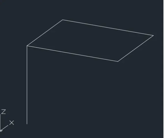
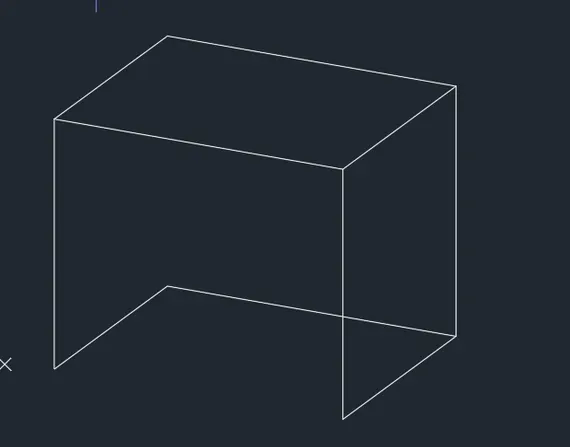
- Click 'LINE' and draw the given element drawing.
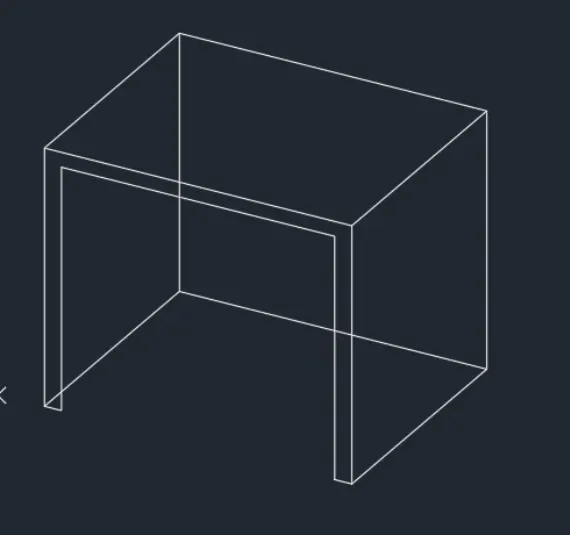
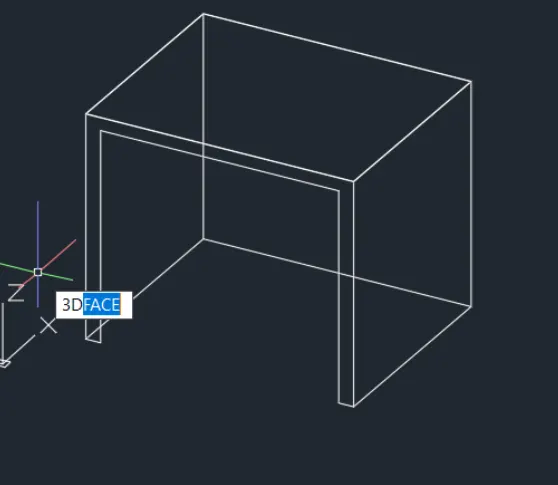
- After completeing drawing the lines ,need to hide so that click 3D face command and draw 4 corners and join.
- Then Cliock 'HIDE' command to hide the drawn line.
- After the view in the 'SHADOW' to clear view of the drawing.
- And Once texting and dimenssioning over save the drawing click 'SAVE' to save the text.
- Finally using 'SNIPPING TOOL' to take screenshot of drawing and save picture.
RESULT : 3D MODEL OF GIVEN ELEMENT DRAWING IS DRAFTED AND FIGURE OF DRAWING IS SHOWN IN BELOW ATTACHED FIGURE.
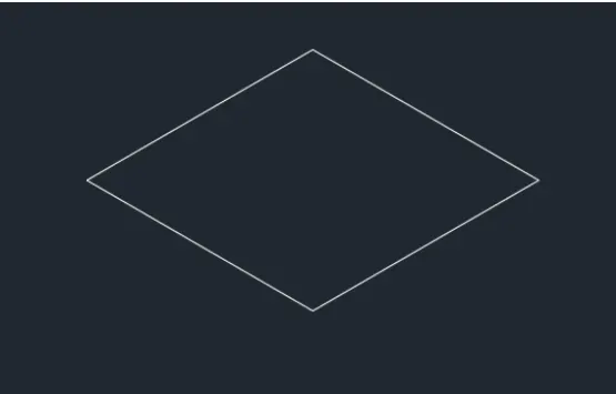
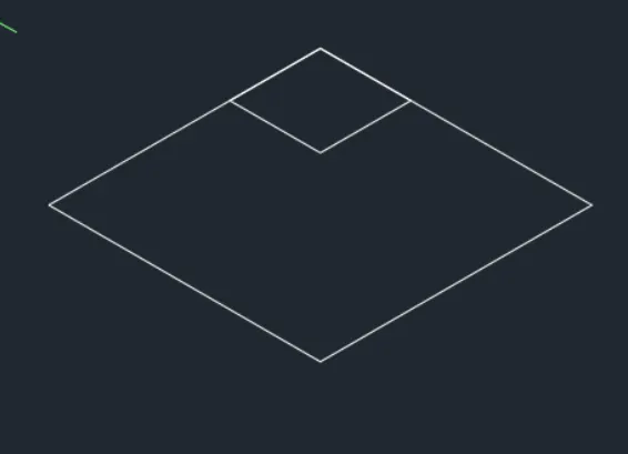
2.AIM: Create a 3D model of an Isolated Footing in Autocad.
PROCEDURE: Creation of 3D models include following steps:
- First Click 3D modeling view in setting.
- Then Change 'UNITS' as per given in drawing.
- Click '3D view' in right corner of the element.
- Click 'LINE' and draw the given element drawing.
- After completeing drawing the lines ,need to hide so that click 3D face command and draw 4 corners and join.
- Then Cliock 'HIDE' command to hide the drawn line.
- After the view in the 'SHADOW' to clear view of the drawing.
- And Once texting and dimenssioning over save the drawing click 'SAVE' to save the text.
- Finally using 'SNIPPING TOOL' to take screenshot of drawing and save picture.
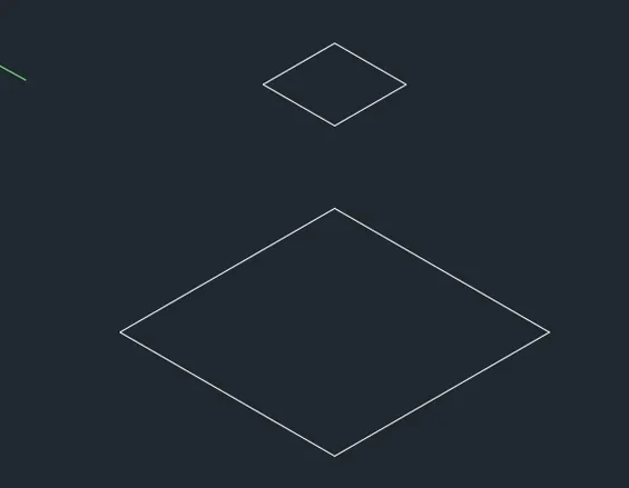
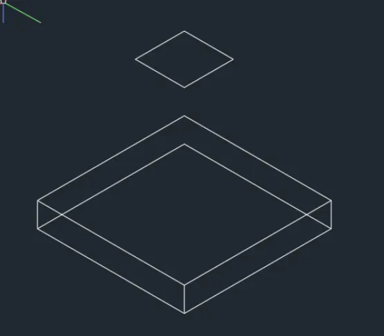
RESULT : 3D MODEL OF GIVEN ELEMENT DRAWING IS DRAFTED AND FIGURE OF DRAWING IS SHOWN IN BELOW ATTACHED FIGURE.

3.AIM: Create a 3D model of AASTHO Type Girder in Autocad.
PROCEDURE: Creation of 3D models include following steps:
- First Click 3D modeling view in setting.
- Then Change 'UNITS' as per given in drawing.
- Click '3D view' in right corner of the element.
- Click 'LINE' and draw the given element drawing.
- After completeing drawing the lines ,need to hide so that click 3D face command and draw 4 corners and join.
- Then Cliock 'HIDE' command to hide the drawn line.
- After the view in the 'SHADOW' to clear view of the drawing.
- And Once texting and dimenssioning over save the drawing click 'SAVE' to save the text.
- Finally using 'SNIPPING TOOL' to take screenshot of drawing and save picture.
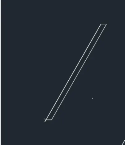
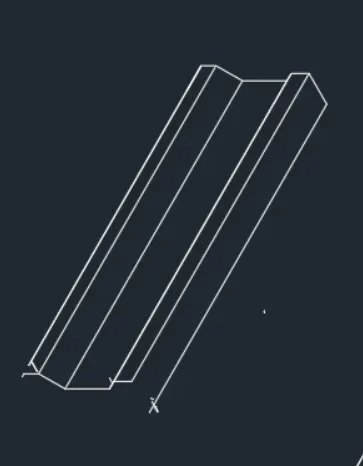
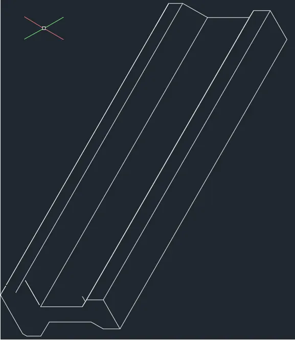
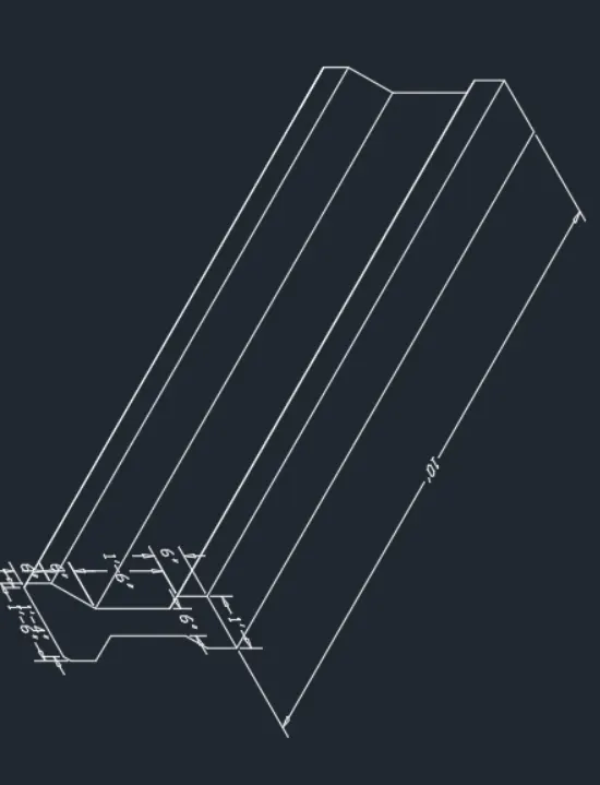
RESULT : 3D MODEL OF GIVEN ELEMENT DRAWING IS DRAFTED AND FIGURE OF DRAWING IS SHOWN IN BELOW ATTACHED FIGURE.
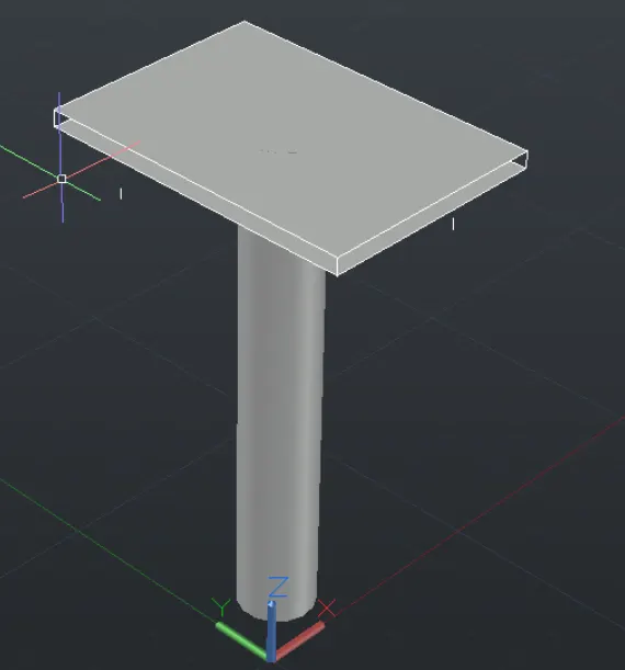
4.AIM: Create a 3D model of Drop Column With Panel in Autocad.
PROCEDURE: Creation of 3D models include following steps:
- First Click 3D modeling view in setting.
- Then Change 'UNITS' as per given in drawing.
- Click '3D view' in right corner of the element.
- Click 'LINE' and draw the given element drawing.
- After completeing drawing the lines ,need to hide so that click 3D face command and draw 4 corners and join.
- Then Cliock 'HIDE' command to hide the drawn line.
- After the view in the 'SHADOW' to clear view of the drawing.
- And Once texting and dimenssioning over save the drawing click 'SAVE' to save the text.
- Finally using 'SNIPPING TOOL' to take screenshot of drawing and save picture.
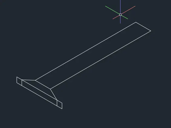
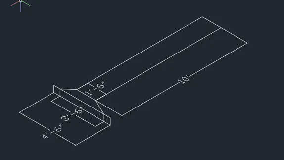
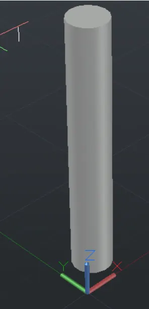
RESULT : 3D MODEL OF GIVEN ELEMENT DRAWING IS DRAFTED AND FIGURE OF DRAWING IS SHOWN IN BELOW ATTACHED FIGURE.
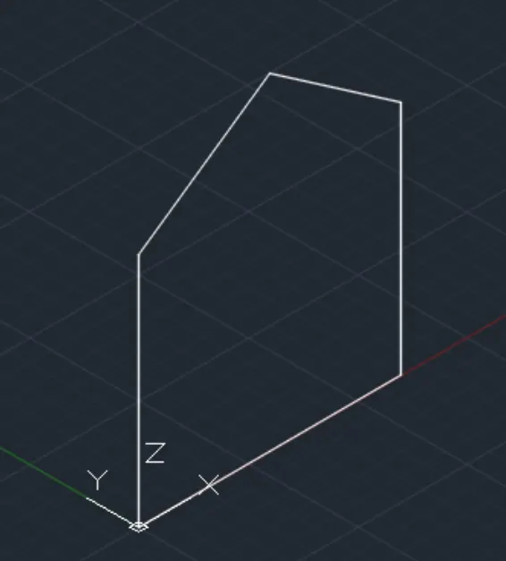
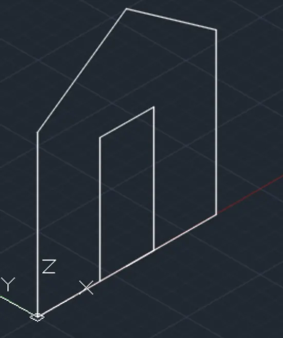
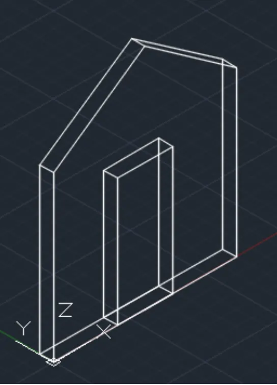
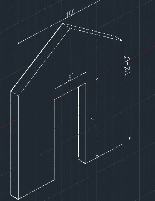
5.AIM: Create a 3D model of Wall in Autocad.
PROCEDURE: Creation of 3D models include following steps:
- First Click 3D modeling view in setting.
- Then Change 'UNITS' as per given in drawing.
- Click '3D view' in right corner of the element.
- Click 'LINE' and draw the given element drawing.
- After completeing drawing the lines ,need to hide so that click 3D face command and draw 4 corners and join.
- Then Cliock 'HIDE' command to hide the drawn line.
- After the view in the 'SHADOW' to clear view of the drawing.
- And Once texting and dimenssioning over save the drawing click 'SAVE' to save the text.
- Finally using 'SNIPPING TOOL' to take screenshot of drawing and save picture.
RESULT : 3D MODEL OF GIVEN ELEMENT DRAWING IS DRAFTED AND FIGURE OF DRAWING IS SHOWN IN BELOW ATTACHED FIGURE.