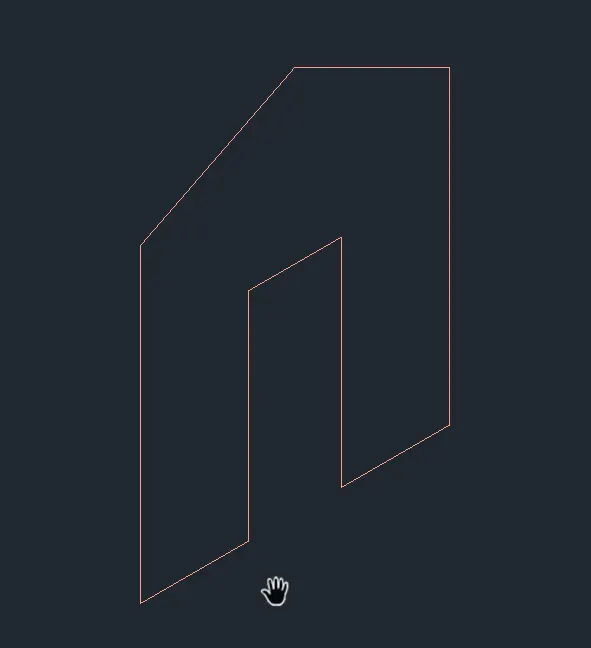
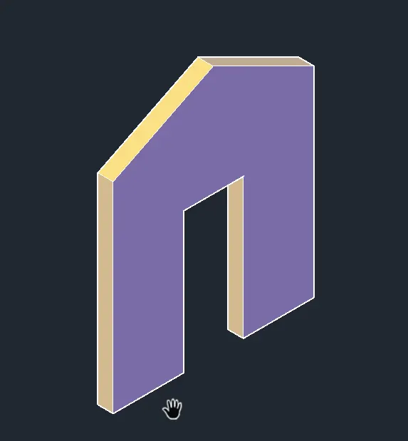
Creating various 3D Models like Furniture, Footing, Girder, Column drop with panel and Gable Wall in AutoCad
Aim: To create a 3D Furniture element using AutoCAD software.
Commands used:
- Extrude
- Offset.
- UCS
- Box
- Union.
- Subtract.
- Move.
- 3d orbit
- Loft
- Sweep.
- Cone.
- Region.
- Boundary.
Procedure :
- Type QNEW in command box, press enter, select the imperial as default setting and select ok.
- Type UN in command box, press enter, select the measuring unit engineering with the precision 0’-0”.
- From setting of status bar change setting from drafting and annotation to the 3D modelling.
- Type LIMAX in command box, press enter, specify max limit as 20’,20’ and press enter.
- Type Z in command box, press enter, type A in command box and press enter.
- From view tab keep on the view cube icon from the ribbon.
- Select home icon of view cube to set the default position of UCS icon.
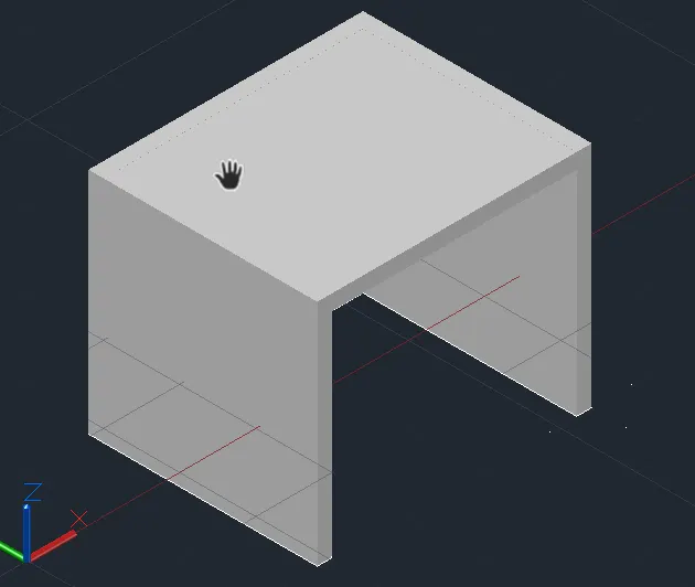
- Now give the command Line and draw the lines as shown below in the figure.
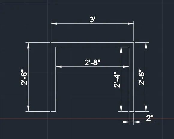
- Using Region command make this a region.
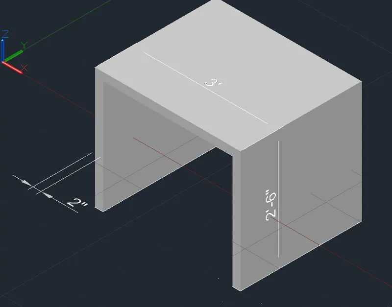
- Now extrude this structure to 2'6"
- create a rectangle from two corner points using the rectang command.
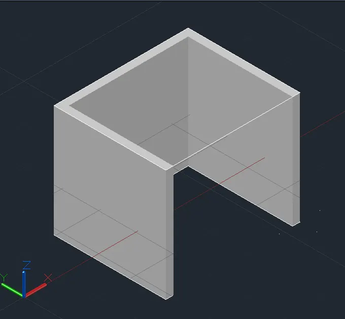
- Now extrude this rectangle in the negative z axis for about 2".
- And last union command and make this both a union.
- Give dimensions in the last.
Result:
Aim: To create a 3d model of isolated footing
Procedure:
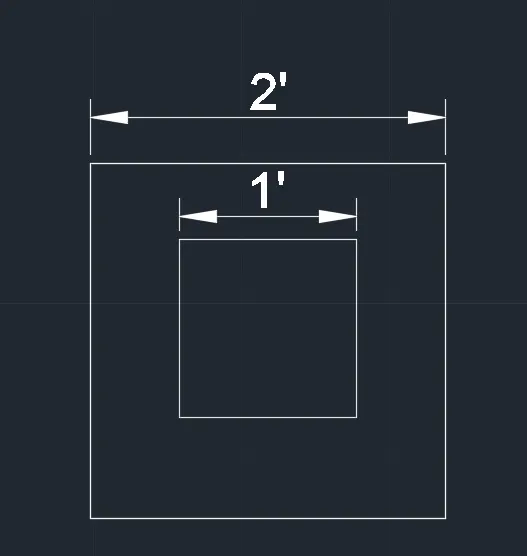
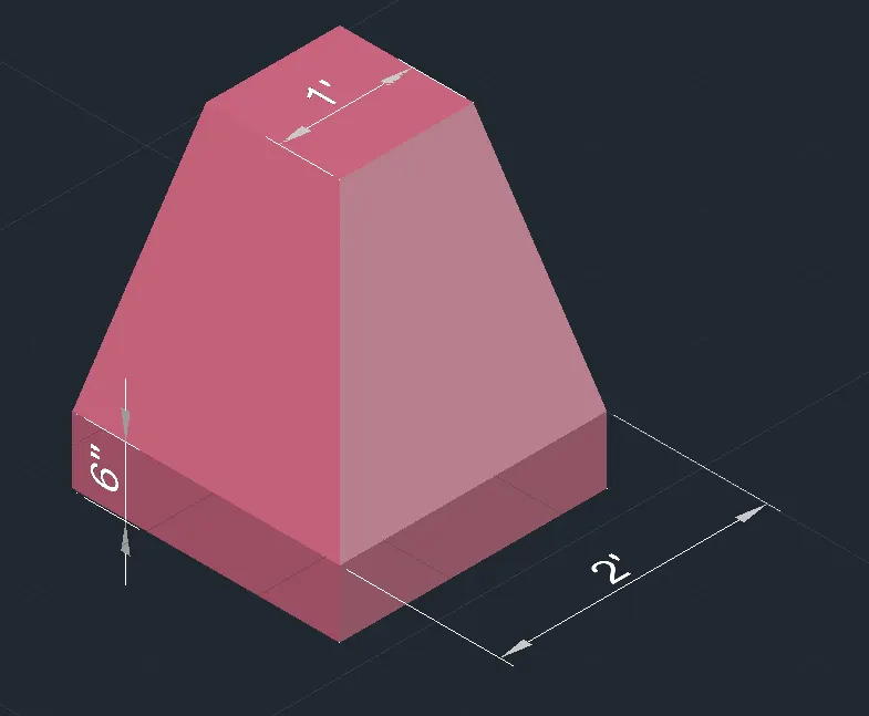
- Create a rectangle of 2' x2' on the top view.Create another rectangle of 1'x 1' on the top view.
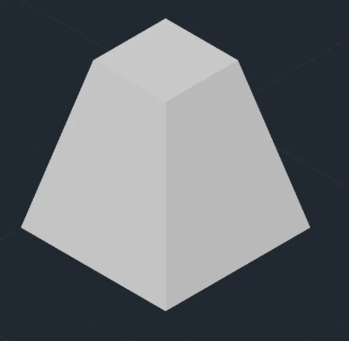
- With command "3do" 3d orbit, orbit the view to a suitable one. With "M" move command move the small rectangle by 2' in z direction with ortho on.
- Click on the loft option from the solid tab and select the two rectangles to loft.
- Again, go to the top view and create rectangle on top of the bigger rectangle of same size Click on extrude from the home toolbar and select the created rectangle and give the extrude height as 6" and the direction of extrusion is pointed by the mouse.
- Give dimension to the structure.
Result:
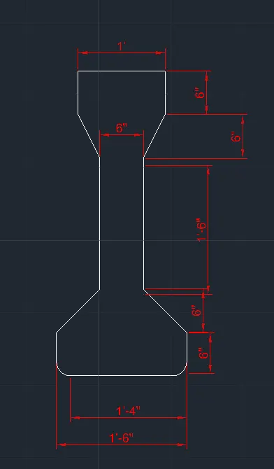
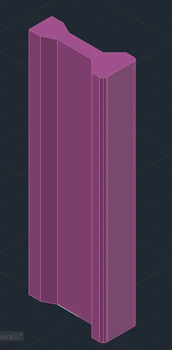
Aim: To create a 3d model of AASTHO type girder using AutoCAD 3d.
Procedure:
- select the TOP view
- command : L (line )
- select start point
- length specify next point @1'-6" ,0
- length specify next point @ 0,6"
- press : enter
- command : L (for line )
- select the start point
- length specify next point @0,6"
- length specify next point @ 6"<135
- length specify next point @0,1'6"
- length specify next point @6"<135
- length specify next point @0,6"
- length specify next point @0,6"
- length specify next point @1',0
- length specify next point @0,-6"
- legth specify next point @0,-1'6"
- then click on closed
- press : ENTER
- go to the ANOTATION TAB
- select the DIMENSION
- and give the dimension to the object
Result:
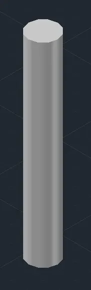
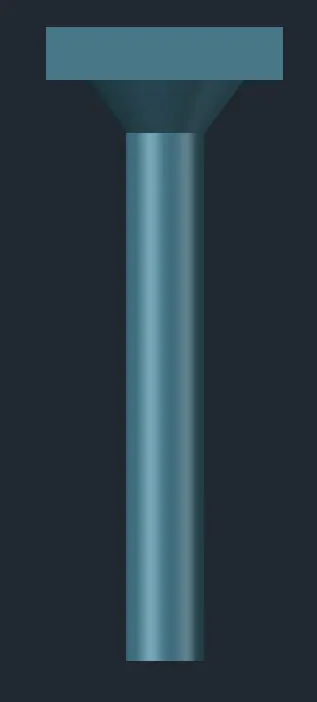
Aim: To draw the 3d model of a drop column with panel section and show its isometric view.
Procedure:
-
Create a circle of diameter 1'6" in the top view.
-
Create a region-by-region command and select the rectangle Extrude it with extrude in home toolbar and give a distance of 10'
-
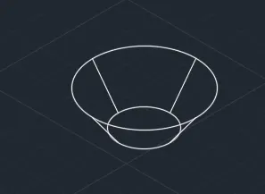
Create a cone by clicking on cone from the home toolbar Click on diameter and give the base diameter as 1'6".
-
Click on top radius and give the value as 1'6" and give the height of the cone as 1"
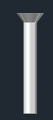
- Place the frustum of cone on top of the extruded circle ie the column in the front view, with snap option place such that the center of two objects coincide also place the center of frustum with center of column in the top view.
- in top view, create a rectangle of dimension 4'6" x4'6" Extrude it to a height of 6".
- In the top view place the rectangle at the center of cone and also adjust in the front view or give move command and give the coordinate
as 0,10',0 as the rectangle is at bottom in the front view.
Result:
Aim: To draw a 3d model of wall.
Procedure :
- command : L (for line )
- select the start point
- length specify next point @3'6",0,0
- length specify next point @0,0'.7'
- length specify next point @3',0,0
- length specify next point @0,0,-7'
- length specify next point @3'6",0,0
- length spcify next point @3'6",0,0
- length spcify next point @0,0,10'
- press : enter
- command : L (for line )
- select the start point as a midpoint of
- length specify next point @0,0,12'6"
- press enetr
- by using line command join the lines as shown in fig
- go to the ANOTATION tab
- click on DIMENSION
- and give the dimension
- press : enter
- command :REGION
- Select the object
- press : enter
- command : CONCEPTUAL
- Press : ENTER
- command : X (for explode )
- select the object
- give the HEIGHT of explode is 9"
- press : enter
Result: