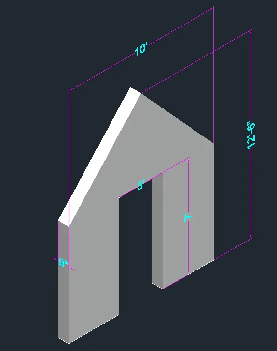
Creating various 3D Models like Furniture, Footing, Girder, Column drop with panel and Gable Wall in AutoCad
AIM : To create various 3D Models like Furniture, Footing, Girder, Column drop with panel and Gable Wall in AutoCad
INTRODUCTION :
- Open autocad application
- Type Qnew and open new drawing
- Set units according to drawing
- Switch ON 3D modeling in work space switching
- Switch on 2D object snap and 3D object snap modes
- Ortho mode is ON
PROBLEM 1 :
AIM : To create 3D furniture element using AutoCad
PROCEDURE :
- Set units to engineering
- Set units in dimensions to engineering
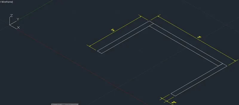
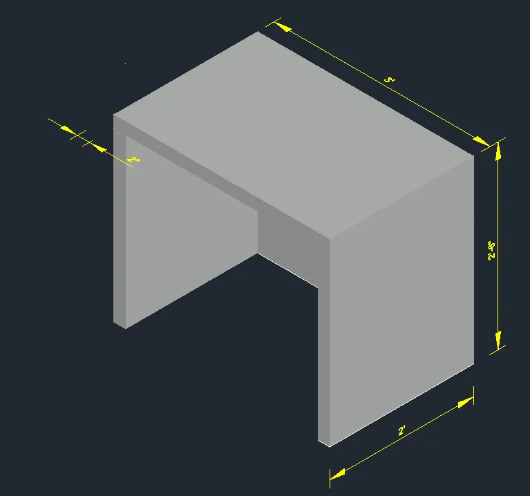
- Take XY plane , draw three rectangles of size 2" x 2', 3' x 2", 2" x 2' as shown below
- Using region tool and boundary tool, create a region in these 3 rectangles
- Now enter extrude in command
- Select the objects and enter the height 2'6"
- Create a rectangle at the top of the object and convert into a region
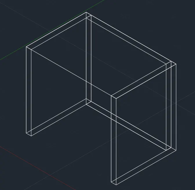
- In the ZX plane create a rectangle of size 3' x 2" at the top as shown below and covert that rectangle also into region
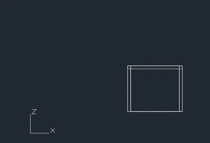
- Set the origin to draw the dimensions
- Using dimlinear dimensions are drawn
RESULT :
3D Furniture element is created and it is shown in shaded view
PROBLEM 2 :
AIM : To create 3D model of isolated footing
PROCEDURE :
- Set units to engineering
- Set units in dimensions to engineering
- Draw a rectangle in XY plane of size 5' x 5'
- Create a region in this rectangle
- Now enter extrude in command
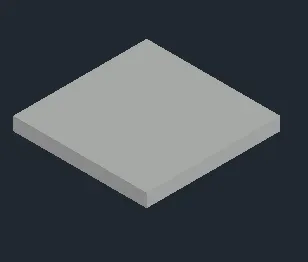
- Select the objects and enter the height 6"
- Select the visual style as shaded
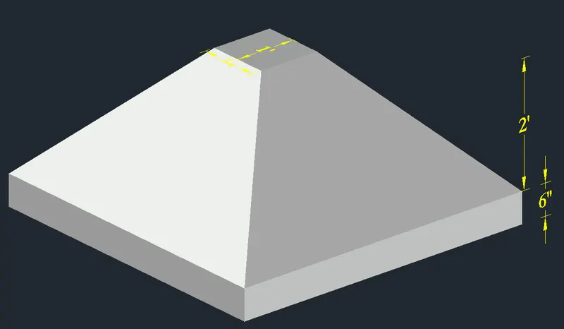
- Select pyramid tool and specify the centre as centre of object
- Enter the base radius as 2.5'
- Click on top radius and enter the value as 6"
- Now enter the value of height as 2' and click ok
- Set the origin to draw the dimensions
- Using dimlinear dimensions are drawn
RESULT :
3D Model of isometric footing is created
PROBLEM 3 :
AIM : To create 3D view of AASTHO type girder
PROCEDURE :
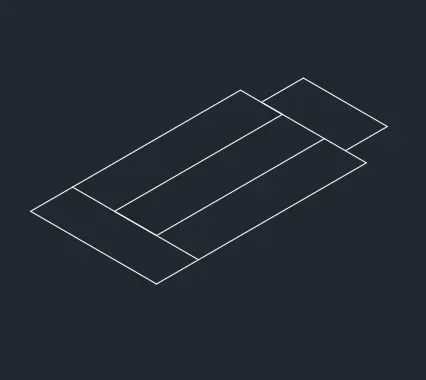
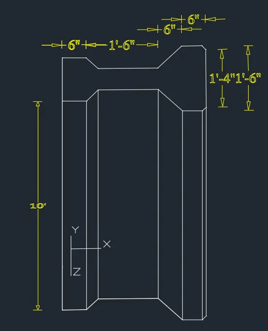
- Draw a rectangle of sizes
- 1'6 x 6"
- 1'6" x 2'
- 1' x 6" (leave 3" on both side of rectangle)
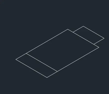
- Now draw another rectangle of size 6" x 2' as shown below
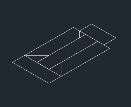
- Create triangles of height and base as
- H=6" , B=6"
- H=3" , B=3"
- Trim off the extra lines as shown below
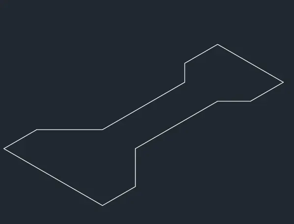
- Using boundary tool create a region of the object
- Now enter extrude in command
- Select the objects and enter the height 10"
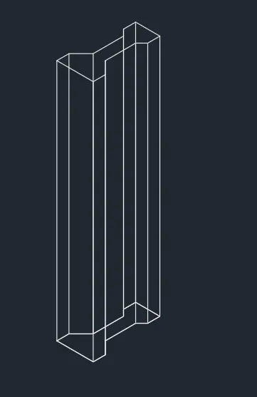
- Enter "Hide" command and press enter
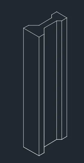
- Enter "Chamferedge" in the command
- Select the edge to be chamfered and enter both the distance 1"
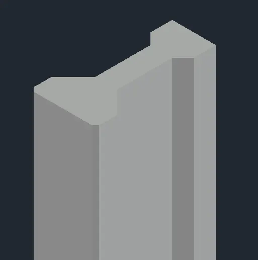
- Set the origin to draw the dimensions
- Using dimlinear dimensions are drawn
RESULT :
3D view of AASTHO type girder is created
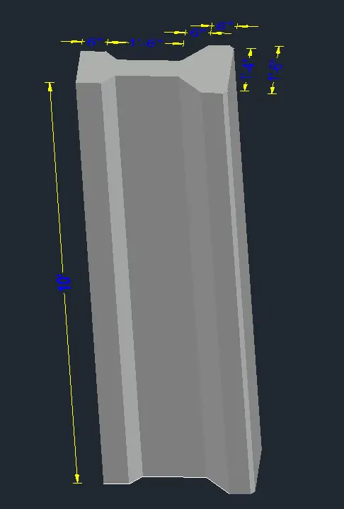
PROBLEM 4:
AIM : To create 3D model of a drop column with panel
PROCEDURE :
- Set units to engineering
- Set units in dimensions to engineering
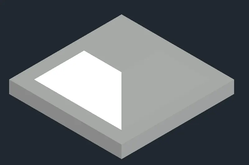
- Draw a two rectangles of size 4'6" x 4' 6" in XY plane
- Convert this rectangle into region
- Now enter extrude in command
- Select the objects and enter the height 6"
- Convert visual into shaded
- Select pyramid tool and specify the centre as centre of object
- Enter the base radius as 21"
- Click on top radius and enter the value as 9"
- Enter height value as 1' and press enter
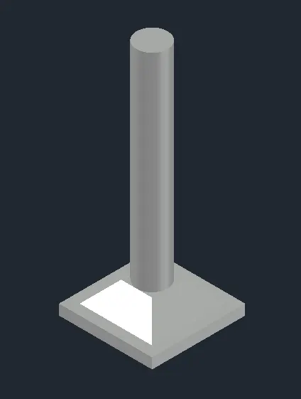
- Now select cylinder tool and select the center of previous object
- Enter the diameter as 1'6" and height as 10'
- Press enter
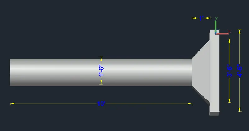
- Set the origin to draw the dimensions
- Using dimlinear dimensions are drawn
RESULT :
3D model of a drop column is created
SHADED VIEW :
2DFRAME VIEW :
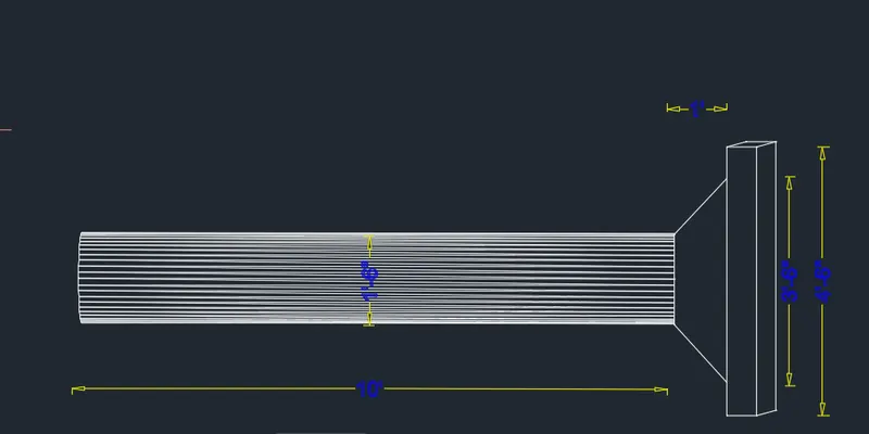
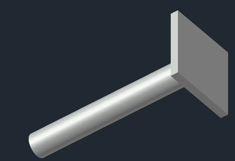
Using 3Dorbit object is rotated and viewed in shaded style
PROBLEM 5 :
AIM : To draw 3D model of wall using AutoCad
PROCEDURE :
- Set units to engineering
- Set units in dimensions to engineering
- Draw a rectangle of size 10' x 9"
- Divide the rectangle into 3 parts
- 3.5' x 9"
- 3' x 9"
- 3.5 x 9"
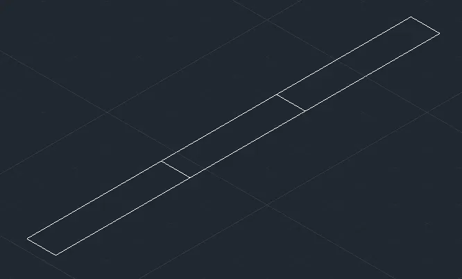
- Now make boundary for regions shown below using "BO" command
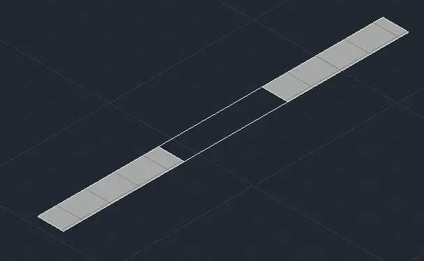
- Now enter extrude in command
- Select the objects and enter the height 7'
- Create a rectangle at the top as shown in the fig
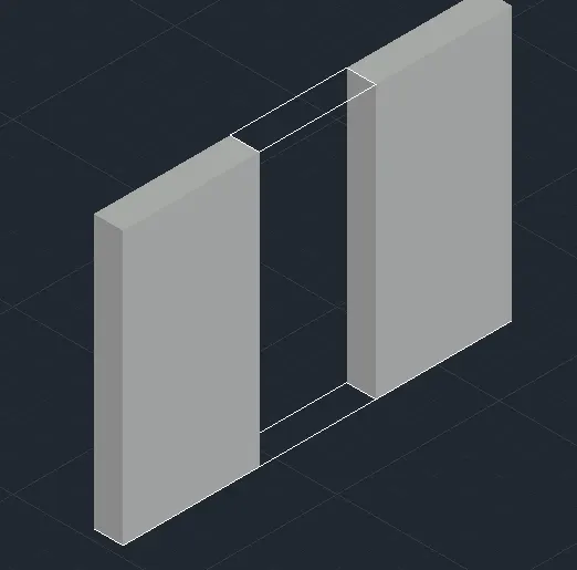
- Convert the rectangle into region and trim off the extra lines below
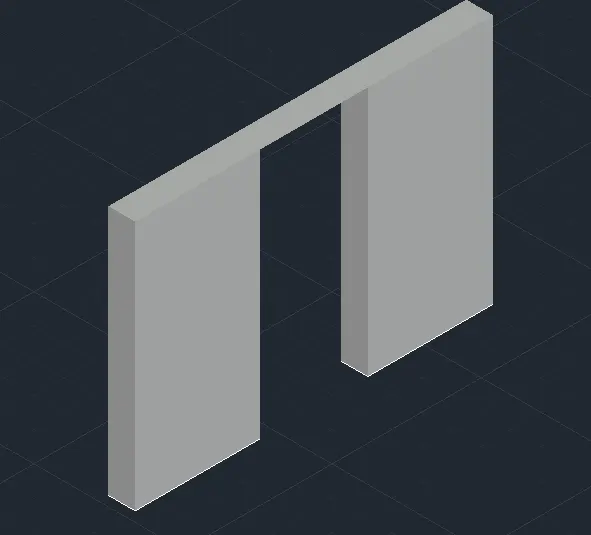
- Now draw a triangle of height 5'6" and base length 10'
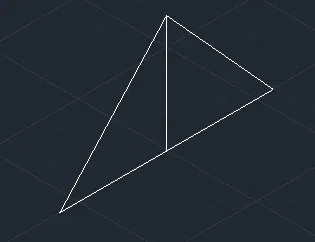
- Convert it into region
- Draw a line of 9" perpendicular to triangle
- Select sweep command
- Select the triangle object and select 9" line as path

- Place this object on the walls

- Set the origin to draw the dimensions
- Using dimlinear dimensions are drawn
RESULTS:
3D Model wall is created