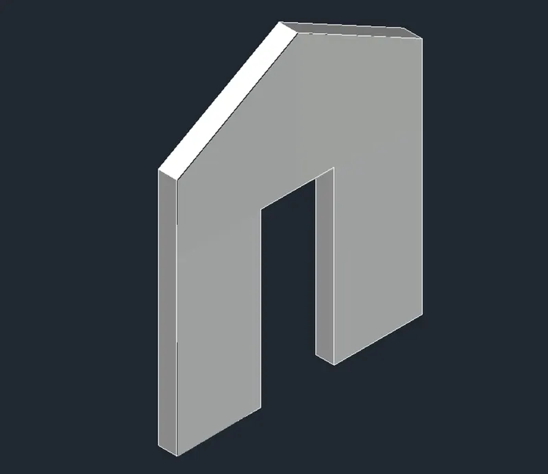
Creating various 3D Models like Furniture, Footing, Girder, Column drop with panel and Gable Wall in AutoCad
Aim:
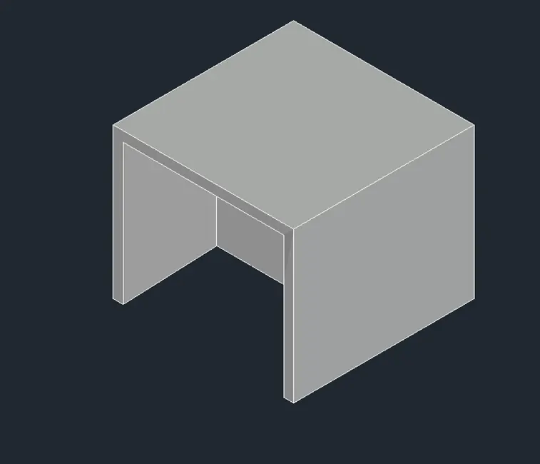
To Create a 3D Furniture element as shown in the Figure.
Introduction :
Various command used while Sketching :
- Line command
- Unit command
- Lim max command
- Limits command
- Zoom command
- Trim command
- Text command
- Extent command
- Rectangle command
- Copy command
- LT command
- Dimension command
- Layer command
- Offset command
- Move command
- REGION command
- EXTRUDE command
- 3DFACE command
PRODUCTRE :
STEP 1 :
- GO to START MENU ,select AutoCAD 2018.
- Enter “UNITS” command in the command tab.
- Open “ Drawing units “ dialogue box , Type as “ENGINEERING ” and precision as 00
- Then click units scale to “ INCHES ”
- Click “OK”.
- Enter “ LIM MAX” command in the command tab.
- Enter new value for Lim max as 100’.
- Enter “zoom” command in the command box.
- Enter “All” command in the command box.
- Enter “LIMITS” command in the command box.
- Specify lower left corner as
- Enter “zoom “ command in the command box.
- Enter “ALL” command in the command box.
STEP :2
- Enter “LINE” command in the command box.
- Give specific value of first point as 0,0,0
- We are using relative rectangular coordinate system
- Give a next specific value of next point as @0,0,2’6”
- Give a next specific value of next point as @0,-3’,0
- Give a next specific value of next point as @0,0,-2’6”
- Give a next specific value of next point as @0,-2’,0
- Give a next specific value of next point as @0,0,2’4”
- Give a next specific value of next point as @0,2’8”,0
- Give a next specific value of next point as @0,0,-2’4”
- Give a next specific value of next point as @0,0,-2’6”
- Give a next specific value of next point as @0,2”,0
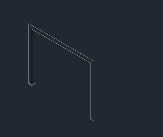
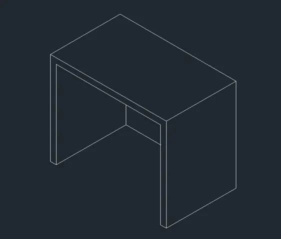
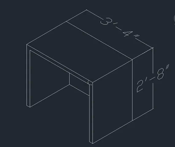
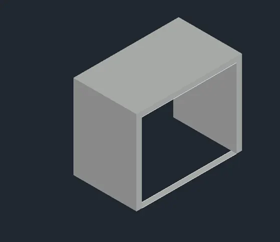
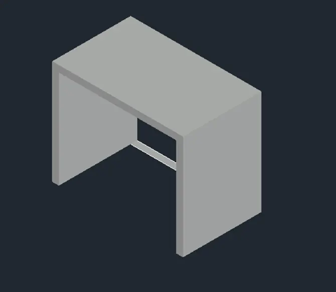
- We created profile of the table.
- Enter “REGION” command in the command box
- Select the option and select the object to create the surface.
- Change the visual style to conceptual
- Enter “EXTRUDE” command in the command box.
- Extrude the created surface in the x-axis at the distance of 2’
- Select the object to extrude the surface
- Enter the extrude distance as 2’
- Change the view to south -east isometric
- Create a reangle size 2’- 8” and 0’-2” at the base of the object created .
- Enter “REGION” command in the command box
- Make the rectangle as surface by using region command
- Enter “EXTRUDE” command in the command box.
- Extrude the surface created in the rectangle at a Hight of 2’-4”
- Enter “3DFACE” command in the command box.
- Select the each corner
- Click “ENTER “
- Enter “HIDE” command in the command box.
- Click the particular face in the drawing , it will be hide
- Go the “2D wire -frame “ change as “SHADE”
- Will get 3d box
- Enter “DIMLINER” command in the command box.
- Select the particular place , mention the dimension as per the drawing
- Finally show the result as for the drawing .
RESULT:
Aim:
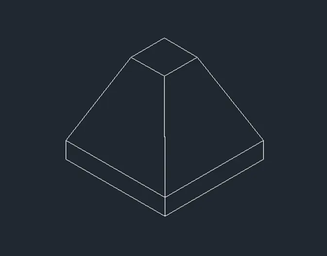
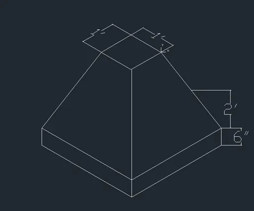
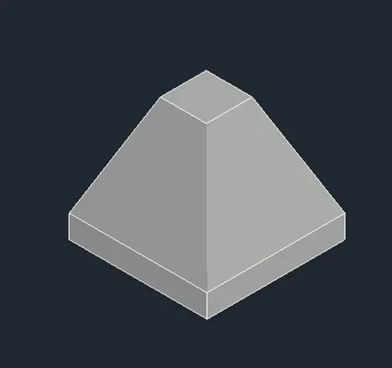
To Create the 3d Model of an Isolated footing as shown in Figure.
Introduction :
Various command used while Sketching :
- Line command
- Unit command
- Lim max command
- Limits command
- Zoom command
- Trim command
- Text command
- Extent command
- Fillet command
- Rectangle command
- Copy command
- LT command
- Dimension command
- Layer command
- Offset command
- Move command
- REGION command
- EXTRUDE command
- 3DFACE command
PRODUCTRE :
STEP 1 :
- GO to START MENU ,select AutoCAD 2018.
- Enter “UNITS” command in the command tab.
- Open “ Drawing units “ dialogue box , Type as “ENGINEERING ” and precision as 00
- Then click units scale to “ INCHES ”
- Click “OK”.
- Enter “ LIM MAX” command in the command tab.
- Enter new value for Lim max as 100’.
- Enter “zoom” command in the command box.
- Enter “All” command in the command box.
- Enter “LIMITS” command in the command box.
- Specify lower left corner as
- Enter “zoom “ command in the command box.
- Enter “ALL” command in the command box.
STEP :2
- Enter “LINE” command in the command box.
- Give specific value of first point as 0,0,0
- Give a next specific value of next point as @3,3,0
- Give a specific Hight as 6”
- Enter “UCS” command in the command box.
- Select the object and place the “UCS” at the top of the box.
- Enter “Pyramid tool “ command in the command box.
- Create the pyramid at the top of the box.
- Enter “LINE” command in the command box.
- Specify the first point at the top first corner of the box and second point at the top second corner point of the box.
- Enter “TOP RADIUS “ command in the command box.
- Enter the top radius as 6”
- Specify the height as 2’
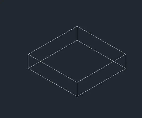
- Enter “3DFACE” command in the command box.
- Select the each corner
- Click “ENTER “
- Enter “HIDE” command in the command box.
- Click the particular face in the drawing , it will be hide
- Go the “2D wire -frame “ change as “SHADE”
- Will get 3d box
- Enter “DIMLINER” command in the command box.
- Select the particular place , mention the dimension as per the drawing
- Finally show the result as for the drawing .
RESULT:
Aim:
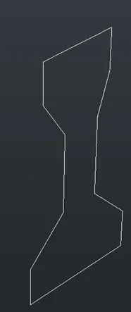
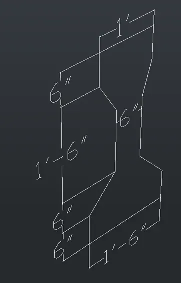
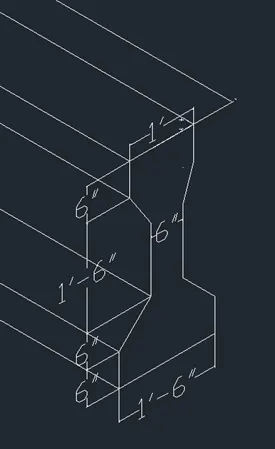
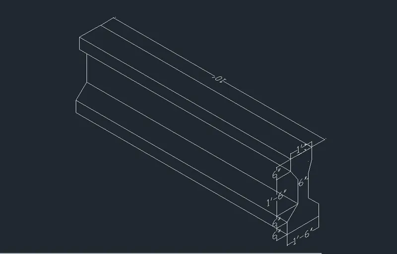
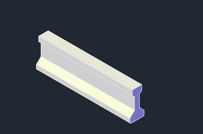
To Create the 3D view of the AASTHO Type Girder.
Introduction :
Various command used while Sketching :
- Line command
- Unit command
- Lim max command
- Limits command
- Zoom command
- Trim command
- Text command
- Extent command
- Fillet command
- Rectangle command
- Copy command
- LT command
- Dimension command
- Layer command
- Offset command
- Move command
- REGION command
- EXTRUDE command
- 3DFACE command
PRODUCTRE :
STEP 1 :
- GO to START MENU ,select AutoCAD 2018.
- Enter “UNITS” command in the command tab.
- Open “ Drawing units “ dialogue box , Type as “ENGINEERING ” and precision as 00
- Then click units scale to “ INCHES ”
- Click “OK”.
- Enter “ LIM MAX” command in the command tab.
- Enter new value for Lim max as 100’.
- Enter “zoom” command in the command box.
- Enter “All” command in the command box.
- Enter “LIMITS” command in the command box.
- Specify lower left corner as
- Enter “zoom “ command in the command box.
- Enter “ALL” command in the command box.
STEP :2
- Enter “LINE” command in the command box.
- We are using relative rectangular coordinate system
- Give specific value of first point as 0,0,0
- Give a next specific value of next point as @0,0,6
- Give a next specific value of next point as @6<0,6
- Give a next specific value of next point as @0,0, 1’-3”
- Enter “UCS” command in the command box.
- Select “Z- axis
- Specify point on positive portion of “Z- axis” as the negative side of “Z- axis”
- Enter “LINE” command in the command box.
- Create line specify point at the last point of the line created .
- Give a next specific value of next point as @3<0, -3
- Change the “UCS” to “UCS WORLD”
- Give a next specific value of next point as @0,0,6”
- Give a next specific value of next point as @0,0,-6
- Enter “UCS” command in the command box.
- Change the “UCS”
- Specify point on positive portion of “Z- axis” as the negative side of “Z- axis
- Enter “LINE” command in the command box
- Create line specify first point at the last point of the line created .
- Give a next specific value of next point as @3<0, -3
- Change the “UCS” to “UCS WORLD”
- Give a next specific value of next point as @0,0,6”
- Give a next specific value of next point as @0,0,-6
- Enter “UCS” command in the command box.
- Change the “UCS”
- Specify point on positive portion of “Z- axis” as the negative side of “Z- axis”
- Enter “LINE” command in the command box
- Create line specify first point at the last point of the line created .
- Give a next specific value of next point as @3<0, 3
- Change the “UCS” to “UCS WORLD”
- Create line specify first point at the last point of the line created .
- Give a next specific value of next point as @0,0,-1’3”
- Enter “UCS” command in the command box.
- Select “X” and enter rotation angle as 90 deg.
- Enter “LINE” command in the command box
- Give a next specific value of next point as @6<0,6
- Change the “UCS” to “UCS WORLD”
- Creating line specific value of next point as 0,0,6
- Give a next specific value of next point as -1’-6”,0,0
- Enter “chamfer” command in the command box.
- Select the multiple option to created to the chamfer
- Chamfer created face at the bottom side both corner at first and second distance as 1”
- Enter “REGION” command in the command box.
- Select the object and created and create the surface
- Change the visual style as conceptual.
- Enter “EXTRUDE” command in the command box.
- Extrude the surface towards “Y -AXIS” at the distance of 10’
- Enter “3DFACE” command in the command box.
- Select the each corner
- Click “ENTER “
- Enter “HIDE” command in the command box.
- Click the particular face in the drawing , it will be hide
- Go the “2D wire -frame “ change as “SHADE”
- Will get 3d box
- Enter “DIMLINER” command in the command box.
- Select the particular place , mention the dimension as per the drawing
- Finally show the result as for the drawing .
RESULT :
Aim:
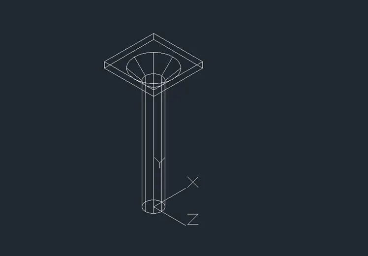
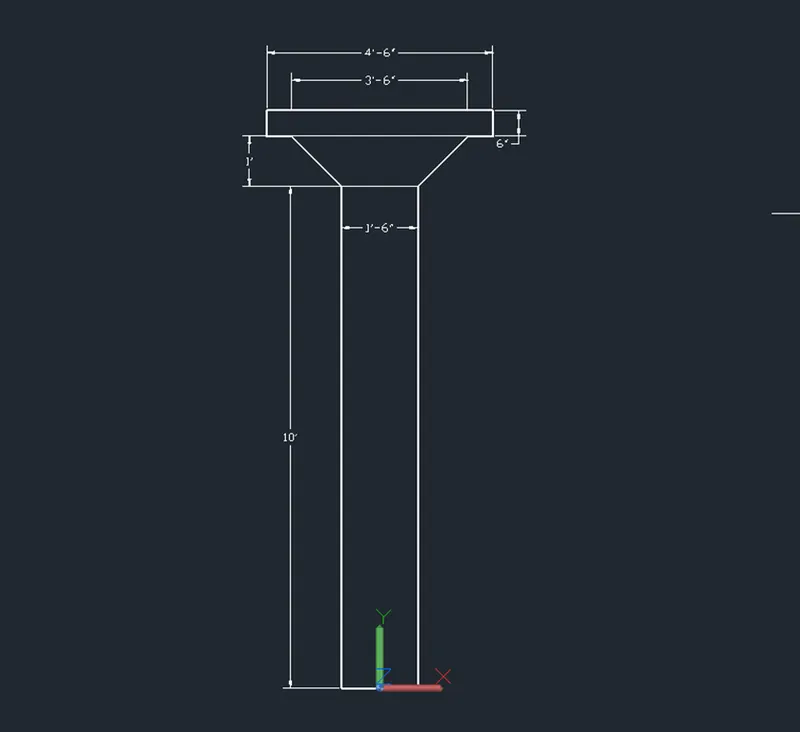
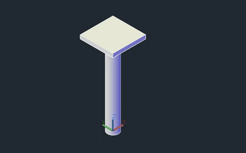
To Create a 3d Model of a drop column with panel as shown in section and isometric view.
Introduction :
Various command used while Sketching :
- Line command
- Unit command
- Lim max command
- Limits command
- Zoom command
- Trim command
- Text command
- Extent command
- Fillet command
- Rectangle command
- Copy command
- LT command
- Dimension command
- Layer command
- Offset command
- Move command
- REGION command
- EXTRUDE command
- 3DFACE command
- Cone command
- Cylinder command
PRODUCTRE :
STEP 1 :
- GO to START MENU ,select AutoCAD 2018.
- Enter “UNITS” command in the command tab.
- Open “ Drawing units “ dialogue box , Type as “ENGINEERING ” and precision as 00
- Then click units scale to “ INCHES ”
- Click “OK”.
- Enter “ LIM MAX” command in the command tab.
- Enter new value for Lim max as 200’.
- Enter “zoom” command in the command box.
- Enter “All” command in the command box.
- Enter “LIMITS” command in the command box.
- Specify lower left corner as
- Enter “zoom “ command in the command box.
- Enter “ALL” command in the command box.
STEP :2:
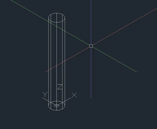
- Enter “cylinder “ command in the command box.
- Specify the center point of the cylinder as 0,0,0
- Specify base radius of 9”
- Specify the height as 10’
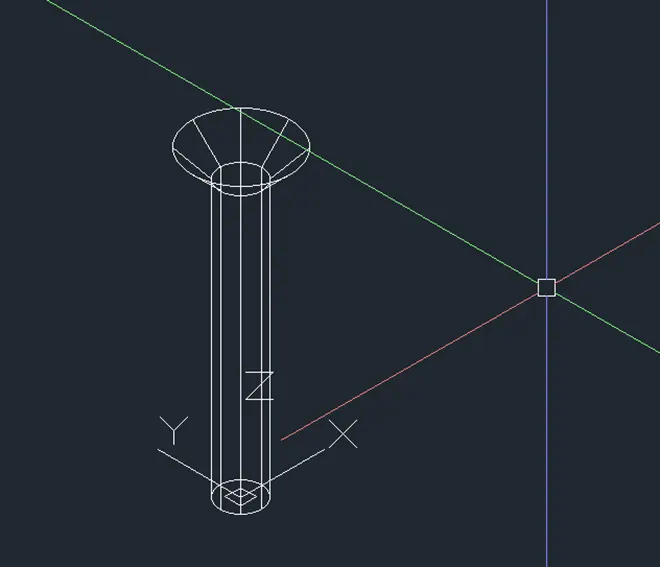
- Enter “Cone” command in the command box.
- Create a cone with specify the center point of the cone at center top of the cylinder .
- Specify the base radius as 9”
- Choose top of the radius
- Specify the radius as 1’-9”
- Specify the height as 1’
- enter “LINE” command in the command box .
- create a rectangular box in top the cone
- specify the first point of the line is center of the cone
- specify the next point of the cone is 4’-6”
- specify the next point of the cone is 4’-6”
- specify the next point of the cone is 4’-6”
- enter “CLOSE”
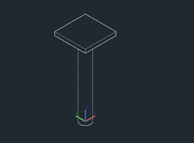
- enter “REGION” command in the command box.
- Create a surface of the rectangle using region command
- Entre “EXTRUDE “ command in the command box.
- Extrude the rectangular box at a height of 6”
- Enter “3DFACE” command in the command box.
- Select the each corner
- Click “ENTER “
- Enter “HIDE” command in the command box.
- Click the particular face in the drawing , it will be hide
- Go the “2D wire -frame “ change as “SHADE”
- Will get 3d box
- Change the “UCS” and check the dimension
- Enter “DIMLINER” command in the command box.
- Select the particular place , mention the dimension as per the drawing
- Finally show the result as for the drawing .
RESULT:
Aim:
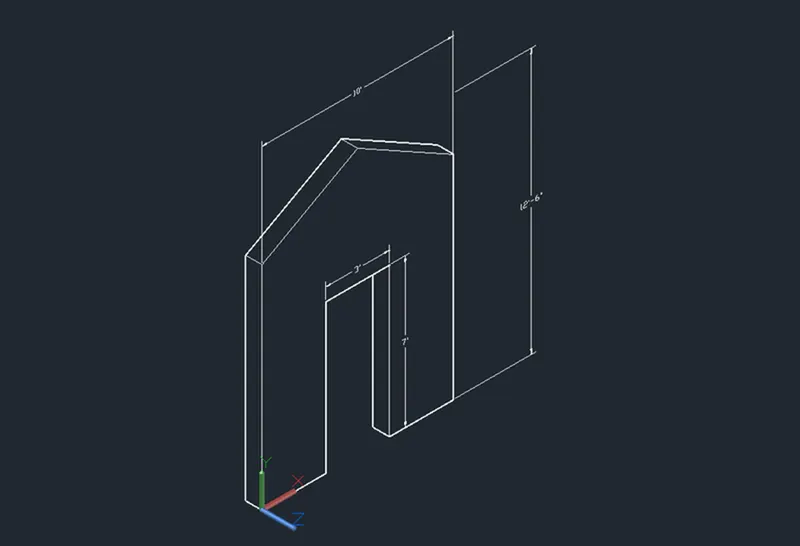
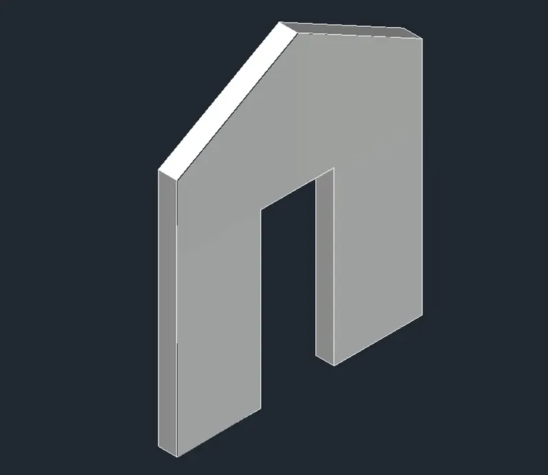
To Create the 3d model of a wall as shown in Figure.
Introduction :
Various command used while Sketching :
- Line command
- Unit command
- Lim max command
- Limits command
- Zoom command
- Trim command
- Text command
- Extent command
- Fillet command
- Rectangle command
- Copy command
- LT command
- Dimension command
- Layer command
- Offset command
- Move command
- REGION command
- EXTRUDE command
- 3DFACE command
PRODUCTRE :
STEP 1 :
- GO to START MENU ,select AutoCAD 2018.
- Enter “UNITS” command in the command tab.
- Open “ Drawing units “ dialogue box , Type as “ENGINEERING ” and precision as 00
- Then click units scale to “ INCHES ”
- Click “OK”.
- Enter “ LIM MAX” command in the command tab.
- Enter new value for Lim max as 100’.
- Enter “zoom” command in the command box.
- Enter “All” command in the command box.
- Enter “LIMITS” command in the command box.
- Specify lower left corner as
- Enter “zoom “ command in the command box.
- Enter “ALL” command in the command box.
STEP :2:
- Enter “LINE” command in the command box.
- Specify the first point of line as 0,0,0
- Switch the work space to 3d modelling and set the view as south -west isometric
- Specify the next point of line @3’4’,0,0
- Specify the next point of line @0,0,7’
- Specify the next point of line @3’,0,0
- Specify the next point of line @0,0,-7’
- Specify the next point of line @3’,0,0
- Specify the next point of line @0,0,10’
- Create a reference line to join the top two end points of the profile.
- Enter “LINE” command in the command box.
- Create line in the “Z-AXIS” from the mid point of the created reference line distance of 2’6” (this reference also)
- Enter ”LINE” command in the command box.
- Create the line top of the point and joint the end point of the reference line.
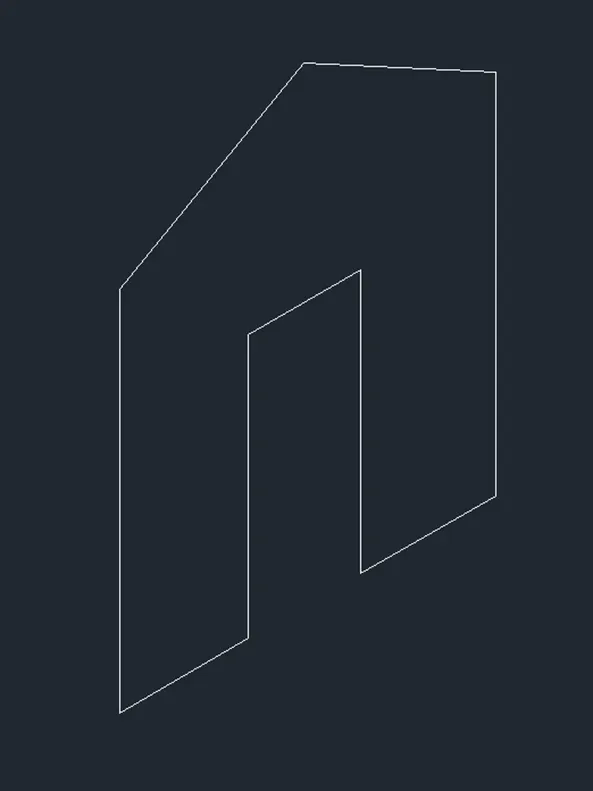
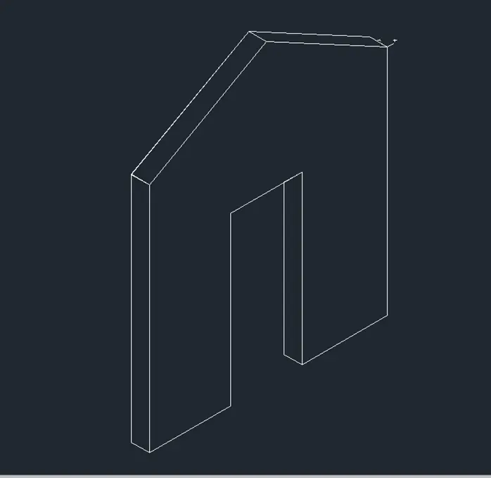
- Enter “REGION” command in the command box.
- Select “object” in the command box.
- And select the whole objects
- Switch the visual style to conceptual.
- Enter “EXTRUDE” command in the command box.
- Extrude the surface at distance of 9” in the “Y-AXIS” direction
- Enter “3DFACE” command in the command box.
- Select the each corner
- Click “ENTER “
- Enter “HIDE” command in the command box.
- Click the particular face in the drawing , it will be hide
- Go the “2D wire -frame “ change as “SHADE”
- Will get 3d box
- Change the “UCS” and check the dimension
- Enter “DIMLINER” command in the command box.
- Select the particular place , mention the dimension as per the drawing
- Finally show the result as for the drawing .
RESULT: