Creating various 3D Models like Furniture, Footing, Girder, Column drop with panel and Gable Wall in AutoCad
1)
AIM
To create a 3D furniture element using autocad.
INTRODUCTION
This 3D furniture element is created using autocad and the procedure is explained in detail in each steps and the commands are used in this drawing are.
COMMANDS USED IN THIS DRAWING
- L- LINE
- F8- ORTHO MODE
- GRIDMODE
- F10 - POLAR TRACKING
- C- CIRCLE
- CO-COPY
- M-MOVE
- O-OFFSET
- F- FILLET
- D-DIMENSION STYLE
- REC-RECTANGLE
- 3F- 3Dface
- surftab1
- surftab2
- revsurf
- box
- cylindrical
- 3DO-3Dorbit
STEP 1
- open autocad file in windows desktop.
- a dialog box will open it shows startup from scratch.
- click the radio button imperial to start the project.
- in command box type gridmode to show the gridmode by typing 1 in the command box
- type F8 to get ortho on.
- type limmax to set the maximum layout.
- type llmits to set the layout.
- press view cube icon to change the view to isometric xyz plane
- type L- LINE command in the command box.
- TYPE UN FOR UNITS and set to Feet and inches.
STEP 2
press the top right corner to open the 3D Modeling.
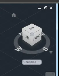
then the UCS icon shows below of plane.
type L line to draw the drawing in the 3d plane.
use the copy option to draw the 3d furniture.
type 3dO - 3d orbit to see the position of the object.
STEP 3
the 3d furniture element is done using 3d modeling.
type 3Dface to surface the drawing.
use the hide option to hide the object to be trimmed.
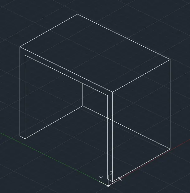
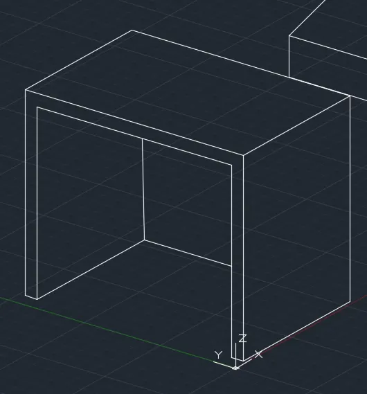
RESULT: The following 3d furniture element is completed as per dimension.
2)
AIM
To create an isolated footing using AutoCAD in a 3d plane.
INTRODUCTION
This 3D furniture element is created using Autocad and the procedure is explained in detail in each step and the commands used in this drawing are.
COMMANDS USED IN THIS DRAWING
- L- LINE
- F8- ORTHO MODE
- GRIDMODE
- F10 - POLAR TRACKING
- C- CIRCLE
- CO-COPY
- M-MOVE
- O-OFFSET
- F- FILLET
- D-DIMENSION STYLE
- REC-RECTANGLE
- 3F- 3Dface
- surftab1
- surftab2
- revsurf
- box
- cylindrical
- 3DO-3Dorbit
STEP1
- open Autocad file on windows desktop.
- a dialog box will open it shows startup from scratch.
- click the radio button imperial to start the project.
- in the command box type gridmode to show the gridmode by typing 1 in the command box
- type F8 to get ortho on.
- type limmax to set the maximum layout.
- type lmits to set the layout.
- press view cube icon to change the view to isometric xyz plane
- type L- LINE command in the command box.
- TYPE UN FOR UNITS and set to Feet and inches.
STEP 2
Press the top right corner icon to open the 3D Modeling.
to see the view of the XYZ plane.
Step 3
Type L-line to draw the drawing.
use the UCS icon to draw the drawing as per dimension
set the view in the top view draw the outer box as per dimension.
and offeset the inner square as per dimension.
and copy the inner square to a height of 2'
as per the dimension the the isolated footing is drawn below.
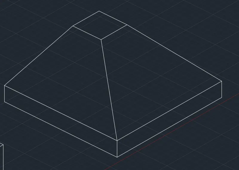
RESULT. the isolated footing is completed as per dimension
3)
AIM
To create a Girder using Autocad.
INTRODUCTION
This 3D view Girder is created using Autocad and the procedure is explained in detail in each step the commands used in this drawing are.
COMMANDS USED IN THIS DRAWING
- L- LINE
- F8- ORTHO MODE
- GRIDMODE
- F10 - POLAR TRACKING
- C- CIRCLE
- CO-COPY
- M-MOVE
- O-OFFSET
- F- FILLET
- D-DIMENSION STYLE
- REC-RECTANGLE
- 3F- 3Dface
- surftab1
- surftab2
- revsurf
- box
- cylindrical
- 3DO-3Dorbit
STEP 1
- open Autocad file in windows desktop.
- a dialog box will open it shows startup from scratch.
- click the radio button imperial to start the project.
- in command box type gridmode to show the gridmode by typing 1 in the command box
- type F8 to get ortho on.
- type limmax to set the maximum layout.
- type llmits to set the layout.
- press view cube icon to change the view to isometric xyz plane
- type L- LINE command in the command box.
- TYPE UN FOR UNITS and set to Feet and inches.
STEP 2
Press the top right corner to open the 3D Modeling.
then the UCS icon shows below of plane.
type L line to draw the drawing in the 3d plane.
use the copy option to draw the 3d furniture.
type 3dO - 3d orbit to see the position of the object.
STEP 3
set the view in XZ plane to draw the drawing.
Draw the Girder drawing as per dimension to set in a view.
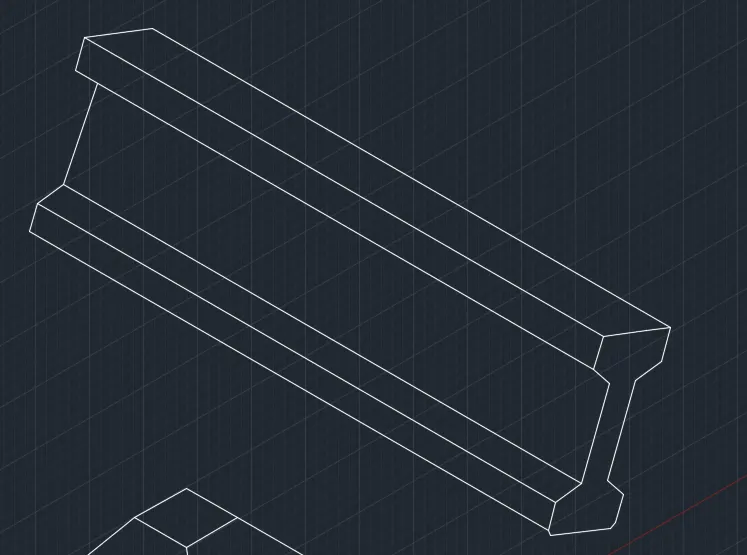
RESULT : The following girder drawing is done as per dimension is completed.
4)
AIM
To create a 3D model Droppanel as per dimension using Autocad.
INTRODUCTION
This 3D Model Droppanel is created using Autocad and the procedure is explained in detail in each step the commands used in this drawing are.
COMMANDS USED IN THIS DRAWING
- L- LINE
- F8- ORTHO MODE
- GRIDMODE
- F10 - POLAR TRACKING
- C- CIRCLE
- CO-COPY
- M-MOVE
- O-OFFSET
- F- FILLET
- D-DIMENSION STYLE
- REC-RECTANGLE
- 3F- 3Dface
- surftab1
- surftab2
- revsurf
- box
- cylindrical
- 3DO-3Dorbit
STEP 1
- open Autocad file in windows desktop.
- a dialog box will open it shows startup from scratch.
- click the radio button imperial to start the project.
- in command box type gridmode to show the gridmode by typing 1 in the command box
- type F8 to get ortho on.
- type limmax to set the maximum layout.
- type llmits to set the layout.
- press view cube icon to change the view to isometric xyz plane
- type L- LINE command in the command box.
- TYPE UN FOR UNITS and set to Feet and inches.
STEP 2
Press the top right corner to open the 3D Modeling.
then the UCS icon shows below the plane.
type L line to draw the drawing in the 3d plane.
use the copy option to draw the 3d furniture.
type 3dO - 3d orbit to see the position of the object.
STEP 3
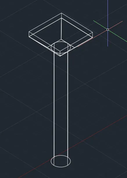
start the diagram to do in the wireframe model to easily complete the diagram.
I have created this diagram using the BOX command option.
type Box in command and press the L- length option and set the width and length of the box.
connect the cylindrical command in the centre of the box
and the height of the cylindrical -11 to
the 2d wireframe model is shown below.
STEP 4
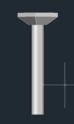
PRESS the 2d wireframe model to shaded option to show in shaded model.
as shown in fig below.
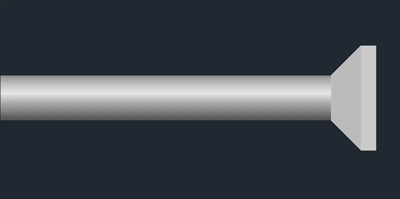
Type 3f-3dface to set the surface of the diagram as shown
STEP 5
TYPE 3DO-3dorbit to set the view as per the question given.
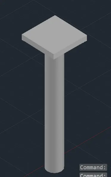
RESULT: The following drop panel is drawn in 3D plane as per dimension is completed
5)
AIM
To create a 3D model wall as per dimension using Autocad.
INTRODUCTION
This 3D model wall is created using Autocad and the procedure is explained in detail in each step the commands used in this drawing are.
COMMANDS USED IN THIS DRAWING
- L- LINE
- F8- ORTHO MODE
- GRIDMODE
- F10 - POLAR TRACKING
- C- CIRCLE
- CO-COPY
- M-MOVE
- O-OFFSET
- F- FILLET
- D-DIMENSION STYLE
- REC-RECTANGLE
- 3F- 3Dface
- surftab1
- surftab2
- revsurf
- box
- cylindrical
- 3DO-3Dorbit
Step 1
- open Autocad file in windows desktop.
- a dialog box will open it shows startup from scratch.
- click the radio button imperial to start the project.
- in command box type gridmode to show the gridmode by typing 1 in the command box
- type F8 to get ortho on.
- type limmax to set the maximum layout.
- type llmits to set the layout.
- press view cube icon to change the view to isometric xyz plane
- type L- LINE command in the command box.
- TYPE UN FOR UNITS and set to Feet and inches.
STEP 2
Press the top right corner to open the 3D Modeling.
then the UCS icon shows below the plane.
type L line to draw the drawing in the 3d plane.
use the copy option to draw the 3d furniture.
type 3dO - 3d orbit to see the position of the object.
STEP 3
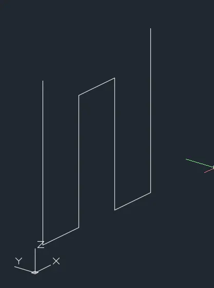
STEP 3
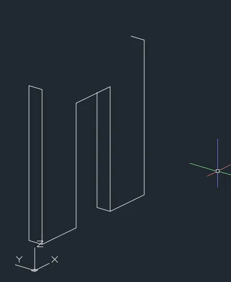
STEP 4
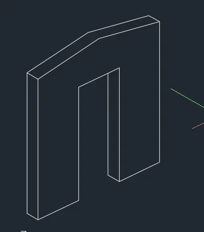
RESULT: The following 3d wall is created as per dimension is completed.