Creating various 3D Models like Furniture, Footing, Girder, Column drop with panel and Gable Wall in AutoCad
1Q:
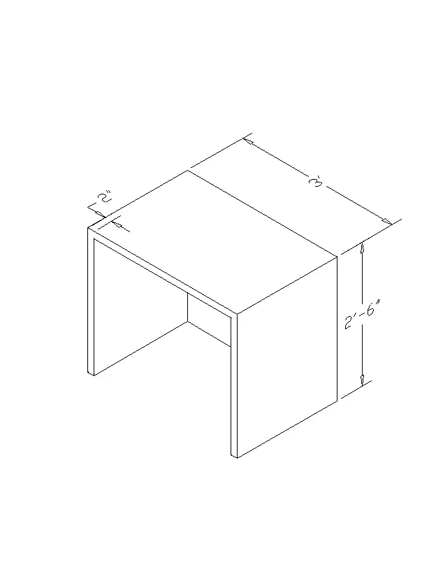
AIM:Create a 3D Furniture element as shown in the Figure. Assume dimensions which are missing.
PROCEDURE:
Type UN and press enter
Under Drawing Units, select Engineering
Now the lower limit is set to 0', 0' and upper limit to 50', 50'
Type Z enter to zoom and A enter to all.
Now in settings selecting 3D Modelling and visual style control to 2D wireframe.
Now draw a solid BOX of 3'x2'6" and height 2'6".
Now using the UCS command set X axis as horizontal, Y axis as vertical.
Draw a line of 2" offset on three sides.
now using the PUSH PULL command give the dimensionn as 2'4".
Now using DIMLIN command give the DIMENSIONS.
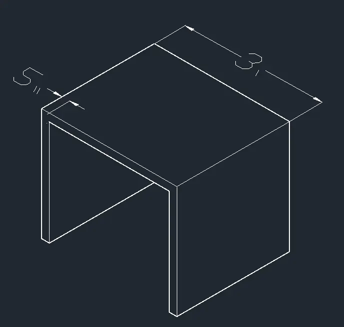
RESULT:Created a 3D Furniture element as shown in the Figure
2Q:
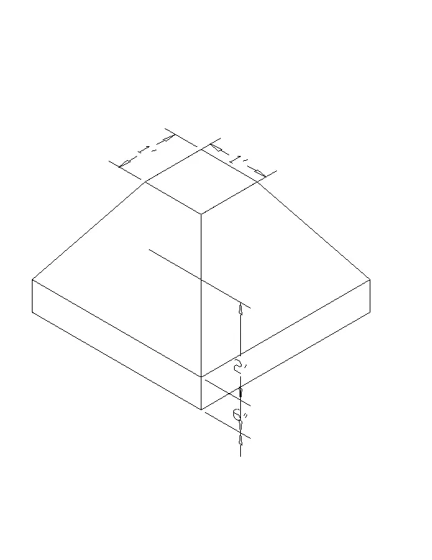
Create the 3d Model of an Isolated footing as shown in Figure.
PROCEDURE:
Type UN and press enter
Under Drawing Units, select Engineering
Now the lower limit is set to 0', 0' and upper limit to 50', 50'
Type Z enter to zoom and A enter to all.
Now in settings selecting 3D Modelling and visual style control to 2D wireframe.
Draw a RECTANGLE of 1'x1'.
Now create the REGION by using region command and select the rectangle.
Now using the EXTRUDE command select the object, select the TAMPER ANGLE of 15 and height of2'.
Now again using the EXTRUDE command extrude 6".
Now using DIMLIN command give the DIMENSIONS.
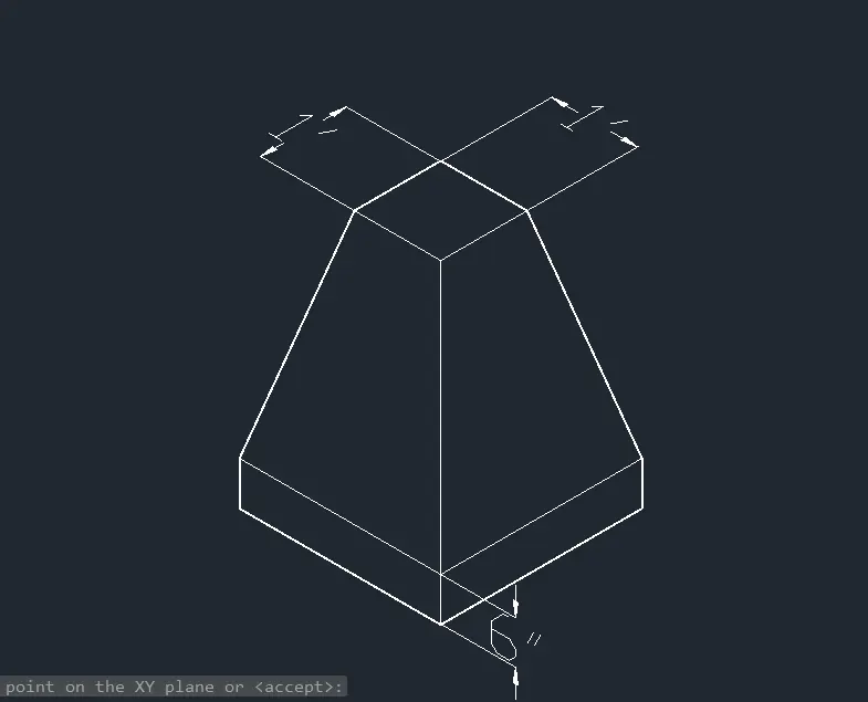
RESULT:Created the 3d Model of an Isolated footing as shown in Figure.
3Q:
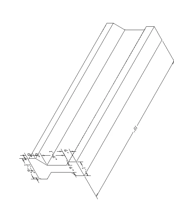
AIM:Create the 3D view of the AASTHO Type Girder.
PROCEDURE:
Type UN and press enter
Under Drawing Units, select Engineering
Now the lower limit is set to 0', 0' and upper limit to 50', 50'
Type Z enter to zoom and A enter to all.
Now in settings selecting 3D Modelling and visual style control to 2D wireframe.
Now using the LINE command draw the AASHO TYPE GRIDER as shown in the figure.
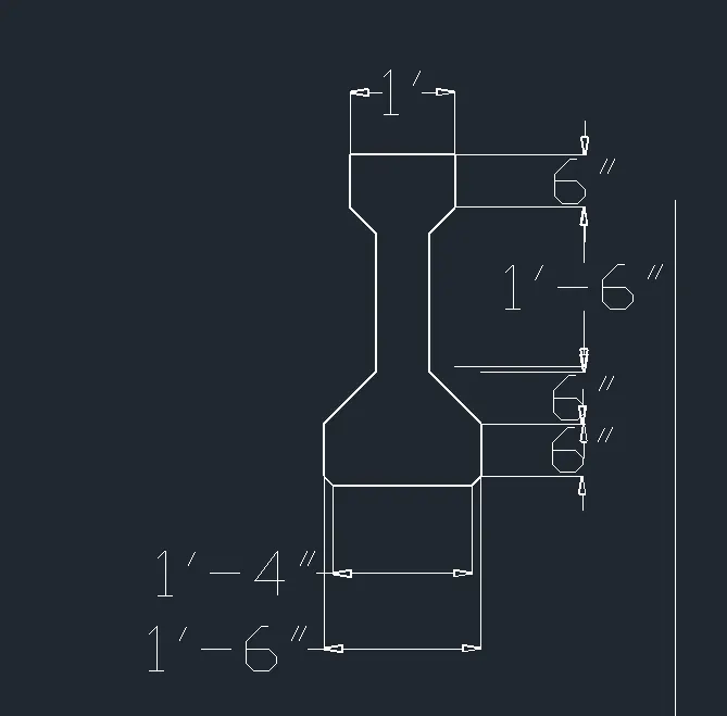
Now create the region by selecting the object REGION is selected.
Now EXTRUDE the given region at the height of 10'.
Now using the DIMLIN command give the dimensions.
RESULT:Created the 3D view of the AASTHO Type Girder.
4Q:
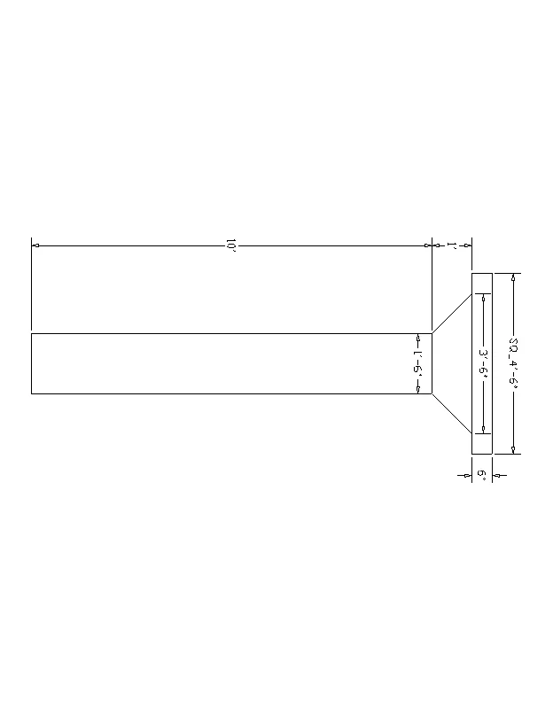
AIM:Create a 3d Model of a drop column with panel as shown in section and isometric view.
Type UN and press enter
Under Drawing Units, select Engineering
Now the lower limit is set to 0', 0' and upper limit to 50', 50'
Type Z enter to zoom and A enter to all.
Now in settings selecting 3D Modelling and visual style control to 2D wireframe.
Draw a RECTANGLE of 4'6" x4'6".
Now create the region by selecting the object REGION is selected.
Now EXTRUDE the REGION at height of 6".
Now using the UCS command set X axis as horizontal, Y axis as vertical.
Now draw a CIRCLE at the center of the rectangle of 3'6",
draw anothe of 1'6" Now using the 3DMOVE move it in 1' through Z axis.
Now using the LOFT command select the both circle and join it.
Now using the EXTRUDE command extrude 9".
Now using the DIMLIN command give the dimension.
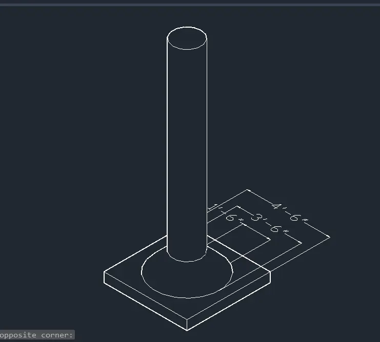
RESULT:Created a 3d Model of a drop column with panel as shown in section and isometric view.
5Q:
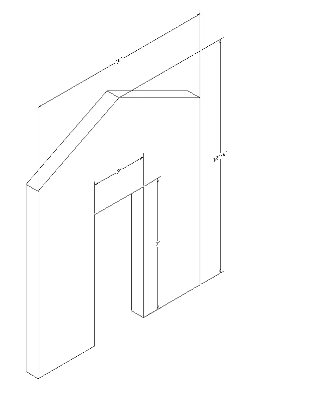
AIM:Create the 3d model of a wall as shown in Figure. Consider wall thickness as 9”.
PROCEDURE:
Type UN and press enter
Under Drawing Units, select Engineering
Now the lower limit is set to 0', 0' and upper limit to 50', 50'
Type Z enter to zoom and A enter to all.
Now in settings selecting 3D Modelling and visual style control to 2D wireframe.
Now using the LINE command draw the figure as shown in below.
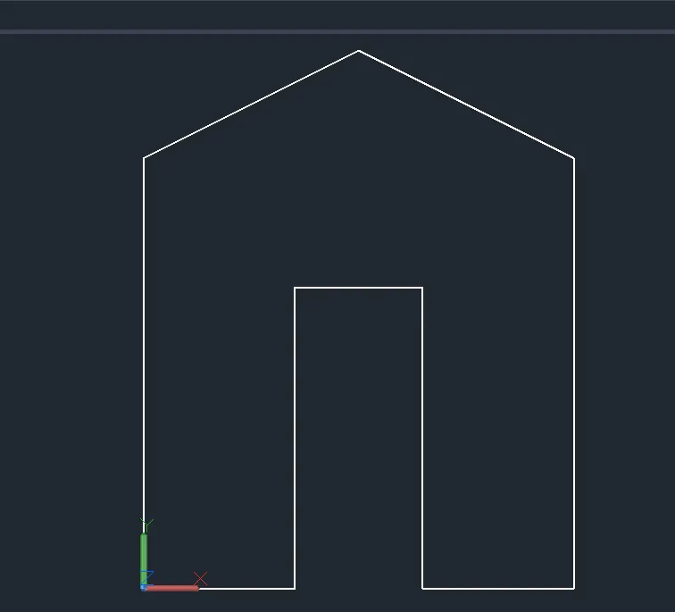
Now create the region by selecting the object REGION is selected.
Now EXTRUDE the given region at the height of 9".
Now using the DIMLIN command give the dimensions.
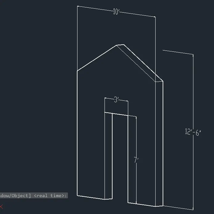
RESULT:Created the 3d model of a wall as shown in Figure. Consider wall thickness as 9”.