Creating various 3D Models like Furniture, Footing, Girder, Column drop with panel and Gable Wall in AutoCad
QUESTION-1:
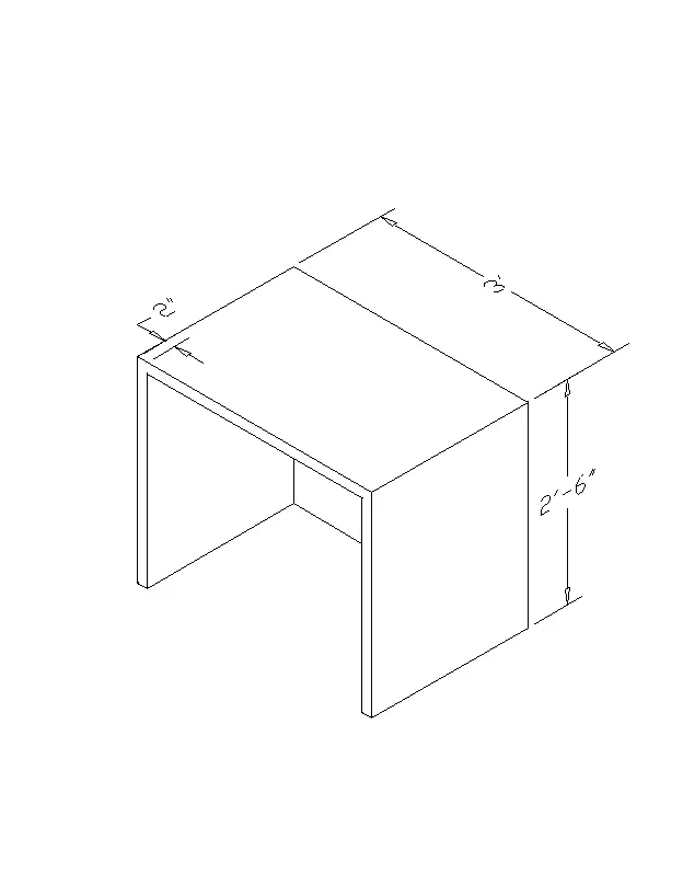
Create a 3D Furniture element as shown in the figure.Assume dimensions that arw missing.
ANSWER:
AIM: Create a 3D Furniture element as shown in fig.
INTRODUCTION:
- In given challenge create a 3D Furniture element using 3D modeling.
- 3D modeling in AUTOCAD includes 3D soilds surfaces meshes ans wireframe objects.
TYPES OF 3D MODELS.
- Several types of 3d modeing are availabe in AUTOCAD . Each of these 3D modeling technologies offers a different set of capabilites.
- Wireframe modeling is useful for initial design iterations and as referance geometry serving as a 3D framework for subsequent modeling or modification.
- Solid modeling is efficient to use easy to combine primitive and extrude profiles,and offers mass properties and sectioning capabilites.
- Surface modeling offers fine control over curved surfaces for precise manipulation and analysis.
- Mesh Modelig provides freeform sculpiting,creasing and smooth capabilites.
COMMANDS USED:
- Units.
- Limits.
- Rectangle.
- Line.
- Extrude.
- UCS.
- Move.
- Subtract.
PROCEDURE:
- Open AUTOCAD.
- In startup settings start from scratch select imperical ( feet and inches)
- Open grid and snap settings.
- Change snap and grid spacing to 1'
- Change major line every grid line to 10
- Turn off adaptive grid.
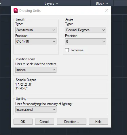
- Type 'UN' in commnad box and press enter.
- Change units type to architetectural and precision to 1'1/16" and insertion scale to inches.
- Chnge the workspace setting of AUTCAD from drafting and annotation to 3d modeling.
STEP-1: Creating Layers.
- Open layer properties and create new layers by clicking on new layer or right click on any layer and select new layer to create new layer.
- Layers are created as follows.
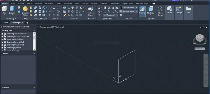
STEP-2: CREATING RIGHT BOX VIEW.
- Start line command.
- Type 0,0,0 and press enter ( Rectangular Coordinate system).
- For next point type 2',0,0, and press enter.
- For next point type @ 0,0,2'6" and press enter ( Relative coordinate system).
- For next point type @2'<180 degree and press enter ( Spherical coordinate system)
- Click on close to cose the box being drawn.
STEP-2: CREATING TOP BOX VIEW.
- Start line command.
- Type 0,0, 2'6" and press enter ( Rectangular coordinate system).
- For next point type 0,3',2'6" and press enter.
- For next point type @ 2',0,0 and press enter( Relative coordinate system).
- For next point type @0,3',0 and press enter ( Relative coordinate system).
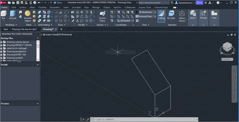
Start line command.
- Type 0,3',2'6" and press enter ( Rectangular coordinate system).
- For next point type @0,0,-2'6" and press enter.( Rectangular coordinate system)
- For next point type @ 0,-2",0 and press enter.
- For next point type @ 0,0,2'4" and press enter.
- For next point type @ 0,-2'8",0 and press enter.
- For next point type @ 0,0,-2'4" and press enter.
- For next point type @ 0,-2",0 and press enter.
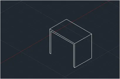
Start line command.
- Type 0,2'10",0 and press enter( Rectangular coordinate system).
- For next point type @ 2',0,0 and press enter ( Relative coordinate system).
- For next point type @ 2',10",0 and press enter ( Relative coordinate system).
- Press enter twice.
- Draw the line connecting top and bottom faces at top corner.
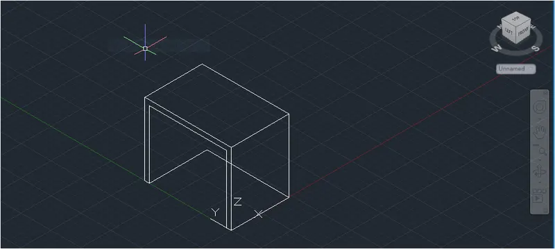
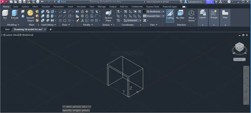
STEP-4: DRAWING FACES
- Use command 3D faces to draw faces.
- Start 3d face command.
- Select 4 corners of face and press enter.
- Change view style control to shaded and check for face.
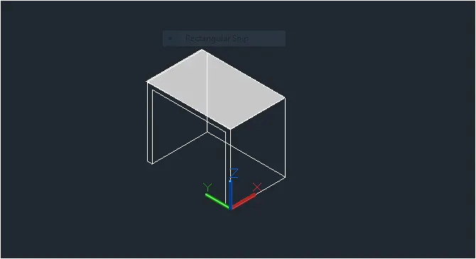
- Follow the same procedure for all the faces of the model.
- Change the view style control to hidden and check for face.
- Change the view style control to sheded and check for face.
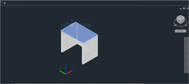
RESULT:
- The 3d model of the furniture equipment is drawn in the above steps.the result consist of model assigned with the layer. the model is drawn using all the coordinate systems.3D face command is used to draw surface to all the faces .result is shown in the three different view style controls such as 2d wireframe, hidden and shaded.
- All dimensions are in feet and inches.
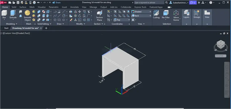
QUESTION-2:
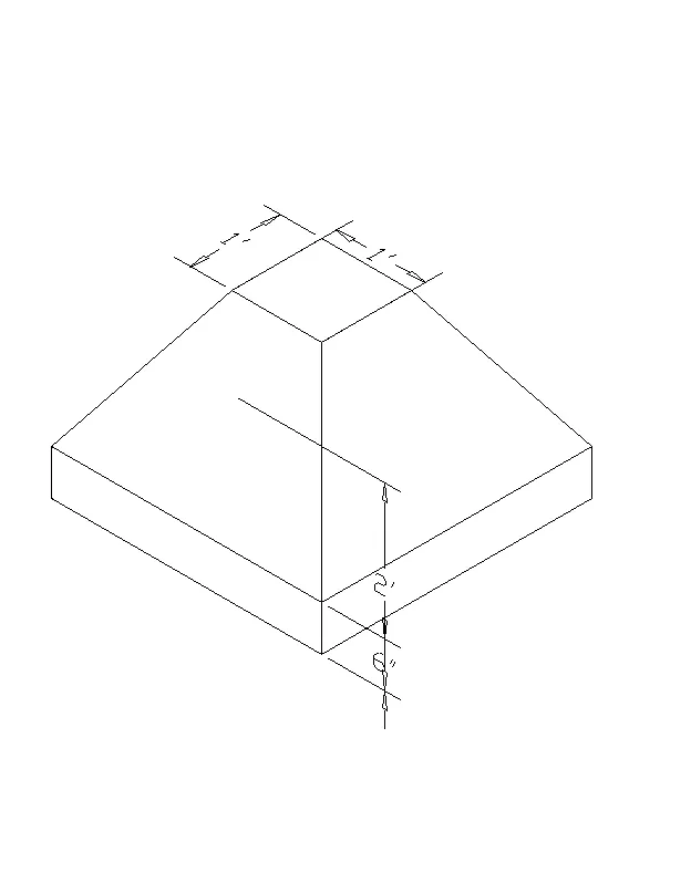
Create the 3D model of an isolated footing as shown in figure.
ANSWER:
AIM:- To draw the 3D wireframe model of an isolated footing as shown in fig.
INTRODUCTION:
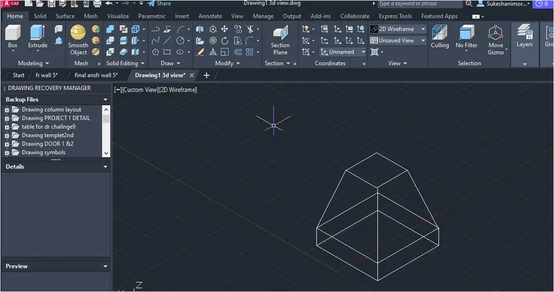
- The 3d model given is an isolated footing is used support a single column .isolated footing are independent footings which are provided for each column.Because of its simplicity and economical natur,it is most commonly used reinforcement footing .this 3d model is of trapexoidal tapered isolated footing.
PROCEDURE:
- Open AUTOCAD.
- In startup setting start from scrach select imperical ( Feet and inches).
- Open grid and snap settings.
- Change snap and grid spacing to 1'
- Change major line every grid line to 10 .
- Turnoff adaptive grid.
- Type un type egeneering and prcision to 0'-0" and scale to inches.
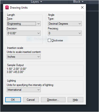
- Change the workspace setting of AUTOCAD from draftiong and annotation to 3d modeling.
STEP-1: CRETAING BOTTOM SURFACE.
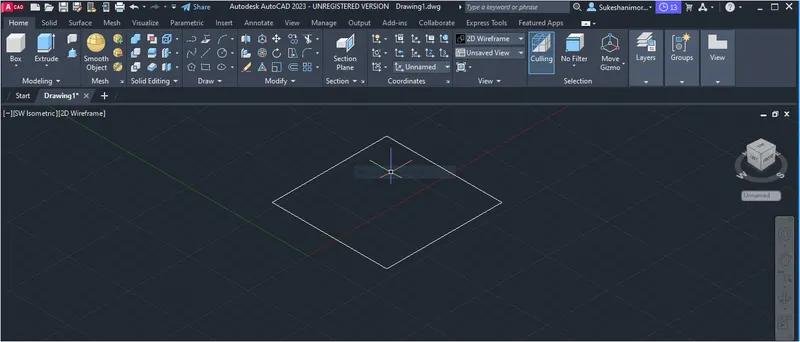
- Start rectangle command.
- Type 0,0,0 and press enter.
- Type @3',3',0 and press enter.
- Press enter twice.
- Type 1',1',0 and press enter.
- Type @ 1',1',0 and press enter.
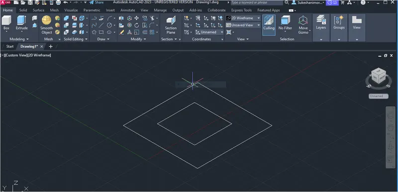
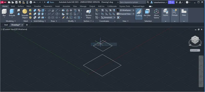
- Using move command move the inner rectangle up to a distance of 2'6"
STEP-2: EXTRUDING BOX.
- Create a region by using region command in both the rectangles.
- Change the view style control to sheded.
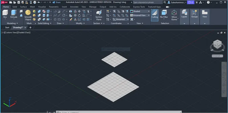
STEP-2(A):
- Change the view style control to 2D wireframe .
- Usin extrude command.
- Extrude the bottom rectangle up to distnace of 6".
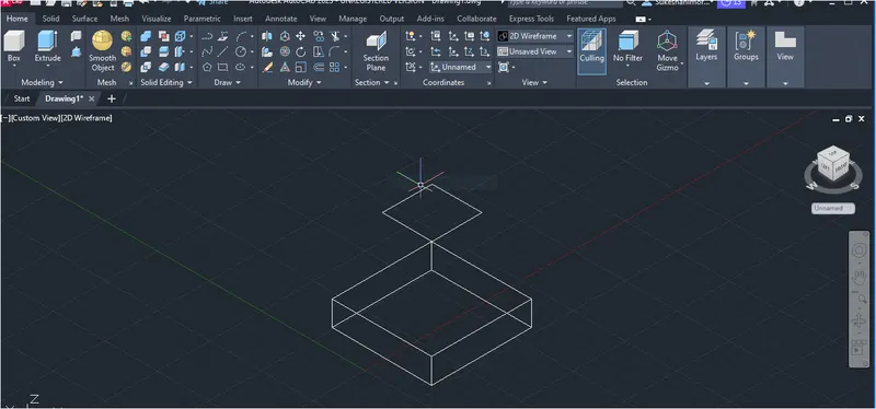
STEP-2(B):-
- Draw another rectangle at the top of the above extrude surface.
- Using extrude command.
- Extrude the rectangle drawn earlier up to distance of 2'
- Click on side grip and select the edge of inner rectangle for tapered shape.
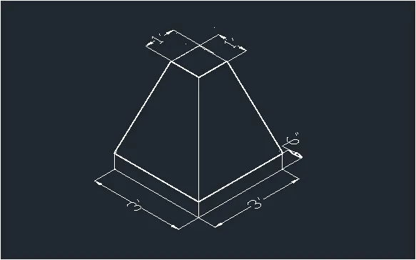
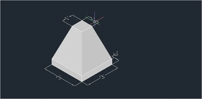
RESULT:
- The 3d model of the isolated tapered footing is drawn in the above steps.the result consist of model assigned with layers.the models is drawn using extrude command region command is used to draw surface to all the faces.result is shown three different view style controls such as 2d wireframe hidden and shaded.
- All dimensions are in feet and inches.
- 2D wireframe model.
 2.Hidden model.
3.Shaded model.
QUESTION-3:
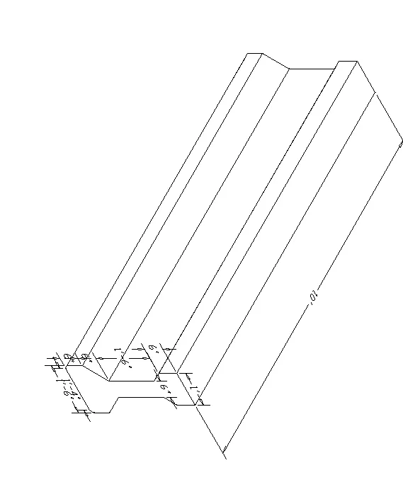
Create the 3D view of the AASTHO type Girder.
ANSWER
AIM:- To draw the 3D wireframe model of an AAStho Type Girder as shown in the figur.
INTRODUCTION:
- The 3D model given is an AASHTO type girder I section.AASTHO girders are classified into 5 different types depending on their dimensions of flange and web.Following figure shows the types of AAStho-Ibeam at different dimensions .as per the dimensions of the given figure the AAshto girder types is ii.
PROCEDURE:
- Open AUTOCAD.
- In startup setting start from scrach select imperical ( Feet and Inches).
- Open grid and snap settings.
- Change snap and grid spacing to 1'.
- Change major line every grid line to 10.
- Turanoff adaptive grid.
- Type un in command box and press enetr.
- Change units type engineering and insertion scale to inches.
- Change the workspace setting of AUtocad from drafting and annotation to 3d Modeling.
STEP-1: CREATING AASTHO TYPE GIRDER.
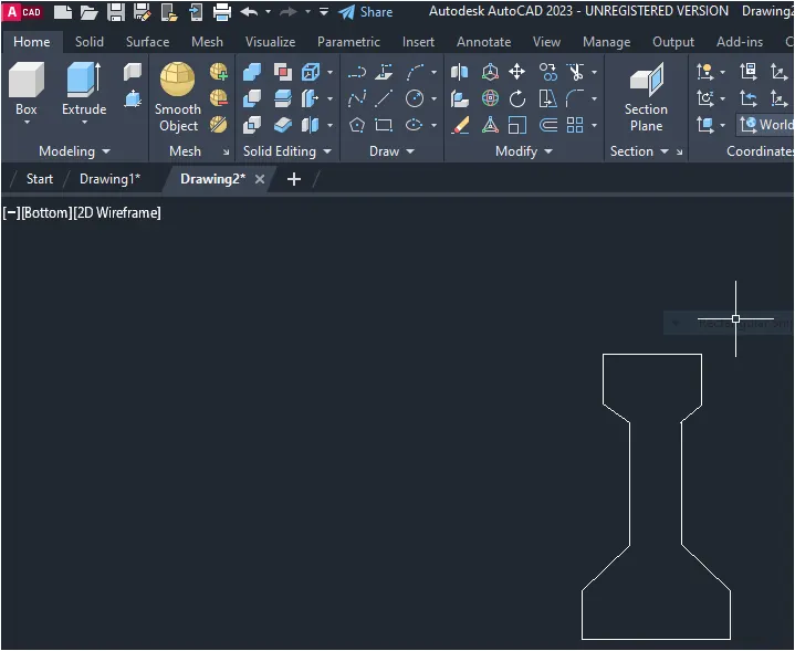
- Start line command.
- Draw a line X direction of distnace 1'6".
- Draw next line upwards to distance of 6",6",1'3",3",6"
- Draw a next line towards left upto distnace of 1'6".
- Draw next line downwords to a distance of 6",3",1'3",6",6"
- Rearrange the lines as per the girder type dimension as shown in the figure.
- Move the both 1'3" line to inside to a diatnce of 6".
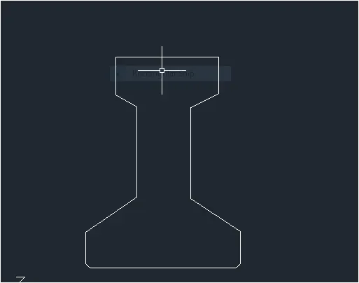
- Connect flange lines with web lines at bottom and top both.
- Use fillet command to curve the bottom edges with radius 1" on both the corners.
STEP-2: CREATING 3D BEAM SECTION
- Create a region by using region command inside the I section.
- Change the view style control to shaded.
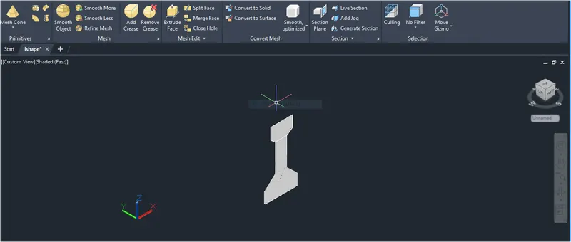
- Go to view cube and click on home .
- Using extrude command.
- Extrude the I section drawn earlier up to distance of 10'
RESULT:
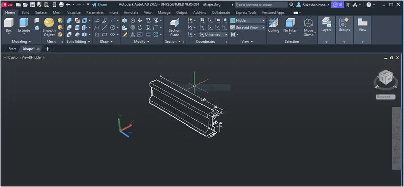
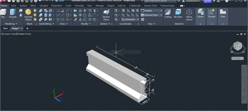
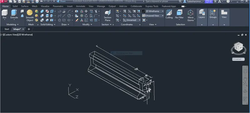
- The 3d model of the I-Section girder as AASTHO type girder is drawn in the above steps. the result consist of model assigned with layers .the model is drawn using extrude command.region command is used to draw surface to all the faces .Result is shown three different view style controls such as 2d wireframe ,hidden and shaded .first the I-Section is drawn in 2d and then region is created and extrude.
- All dimensions are in feet and inches.
1- 2D wireframe model.
2- Hidden model
3. Shaded model.
QUESTION-4:
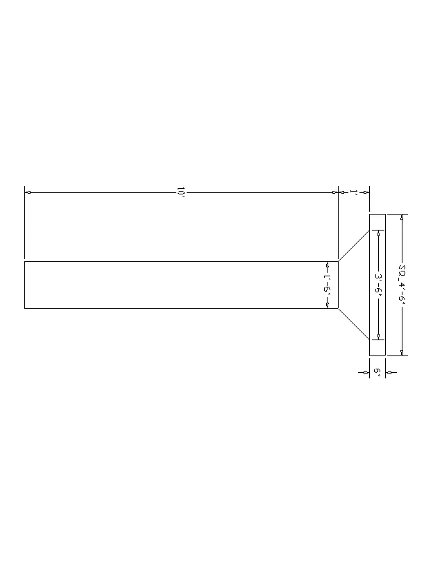
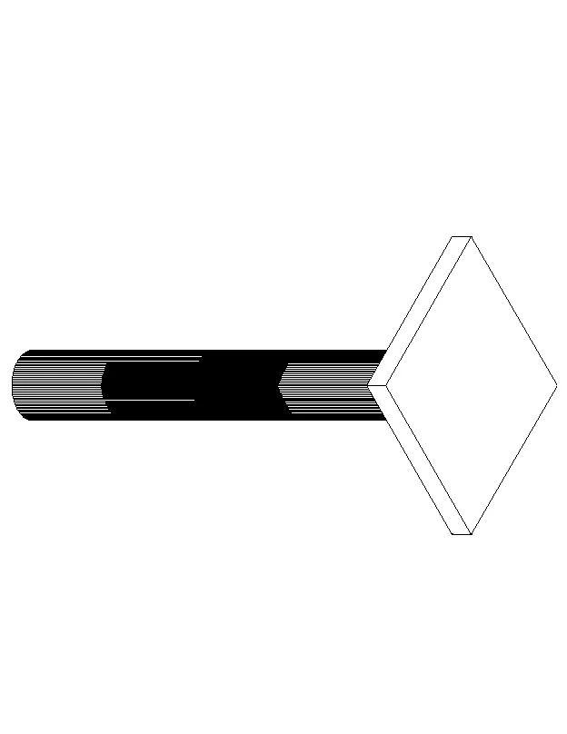
Create a 3D Model of a drop column with the pane as shown in the section and isometric view.
ANSWER:
AIM: To draw the 3d wireframe model of an Drop column as shown in the figure.
INTRODUCTION:
- The 3d model given is a drop column used for construction of flat slabs.Adrop column is used when beam is not required in the design.Drop is a part of the slab around the column which have gretaer thickness than the rest of the slab.The drop column not only eliminates the need of beam but also gives a plain ceiling and great appetence better light diffusion more open rooms.Flat slab is design by two methods.
- Dirct design Method.
- Equivalent frame method.
PROCEDURE:
- Open AUTOCAD.
- In startup setting start from scrach select imperical ( Feet and Inches).
- Open grid and snap settings.
- Change snap and grid spacing to 1'.
- Change major line every grid line to 10.
- Turanoff adaptive grid.
- Type un in command box and press enetr.
- Change units type engineering and insertion scale to inches.
- Change the workspace setting of AUTOCAD from draftiong and annotation to 3d modeling.
STEP-1:
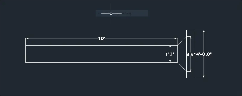
- start line command.
- Type line> draw a line 4'6" > and then line of 6" both the corner point and joint the line.
- Take reference of middle point> draw a line of 3'6"
- Draw other line using dimension given.
- Type dimlin and give dimension.
 STEP-2:
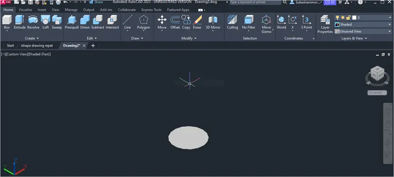
- Go to the default 3D view using the UCS icon.
- Select the circle tool by typing c or circle in the command box.
- Create the circle with a diameter of 1'6" as shown in the fig below.
- Select the region tool and cretae a region of the circle that we cretaed earier.
STEP-3:
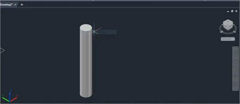
- Select the extrude tool by typing ext or extrude in command box.
- Select the circle and Extrude it tnto the +Z direction.
- Give Extrude height as 10' and skech the column as shown in the figure below.
STEP-4:
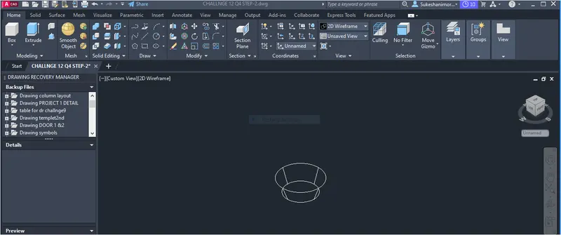
- Select the cone tool from the home ribbon tab.
- Skeh the cone with the base diameter of 1'6".
- Now click on the top radius option and give the value is 1'6"
- Then provide the height of the cones as 1' and skech the cones as shown in the figure below.
STEP-5:
- Go to the Top View using the ucs icon at the top right corner.
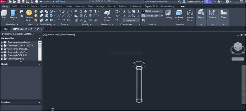
- Select the cone that we cretaed earlier and move it into the extrude circle.
- Now, go to the default 3D view and move the cone from the bottom to the top level at a distance of 10'
- The frustum with the cone has been skeched as shown in the figure below.
STEP-6:
- Go to the top view again using UCS icon.
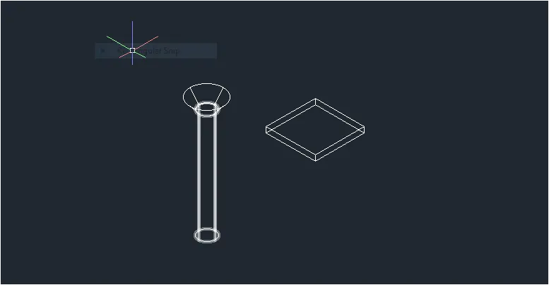
- Select the rectangle tool and draw the rectangle with the dimension of 4'6"*4'6".
- Select the extrude tool and Extrude the recatngle into the +Z direction at a height of 6" as shown in the figure below.
STEP-7:
- Go to the Top View again using the ucs icon.
- Select the extrude rectangle and move it into the extrude circle at the center.
- Go to the default 3D view and move the Extrude rectangle from the bottom to the top at a distnce of 10'.
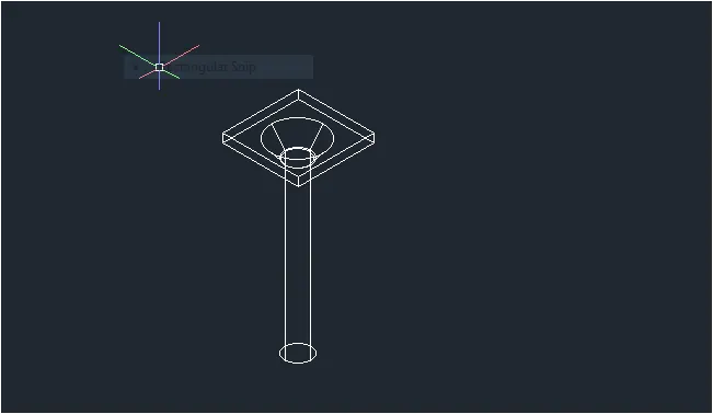
STEP-8:
- After moving the extrude rectangle go to the default 3d view.
- Change the viewing style model from the 2d wireframe to the hidden.
- Now we can see the dropped color witn the panel as shown in the figure below.
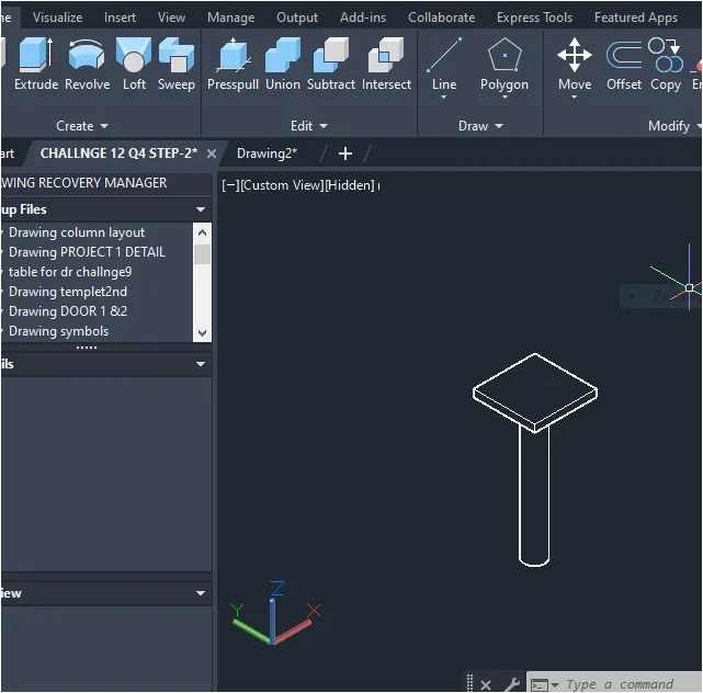
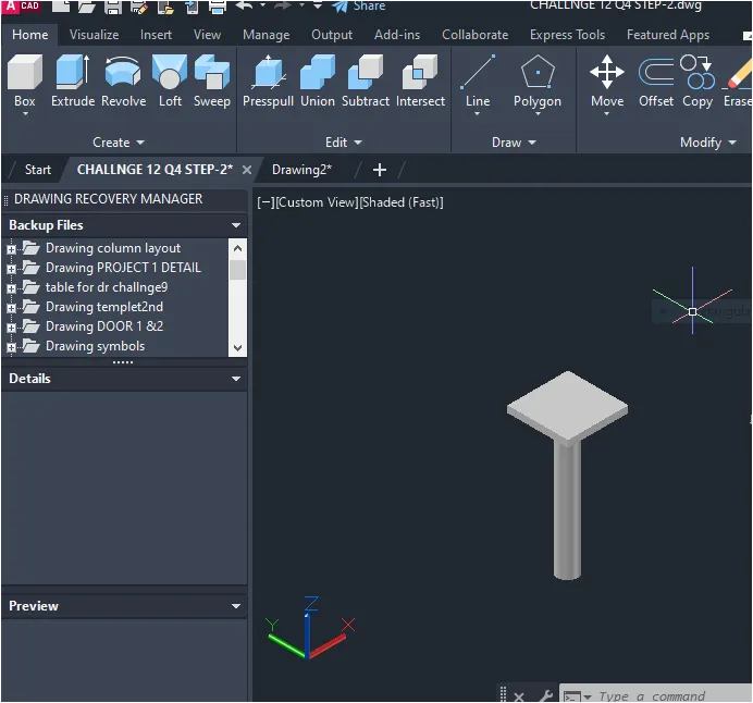
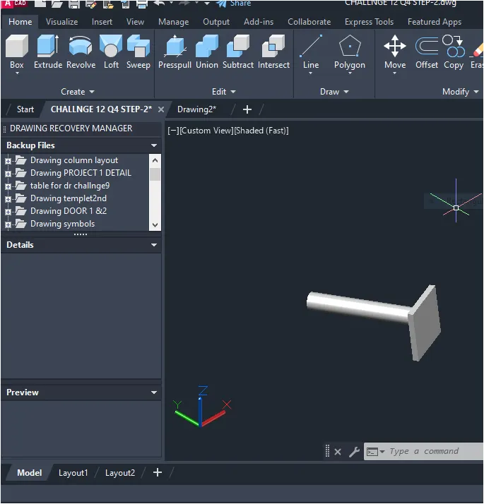
RESULT:
- The 3D model of the Drop column with panel has been skeched successfully as per the drawing
QUESTION-5:
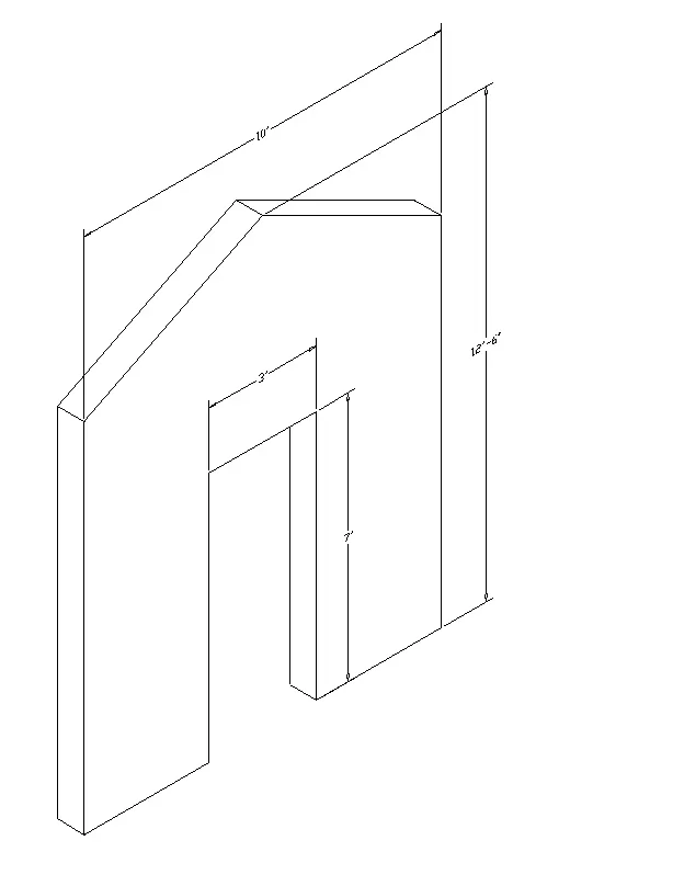
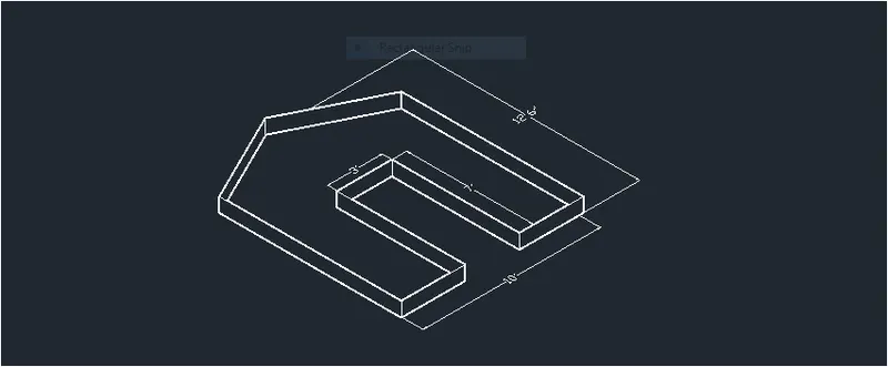
Create the 3d model of a wall as shown in figure.Consider wall thickness as 9"
ANSWER:
AIM: To draw the 3d wireframe model of a wall as shown in figure.
INTRODUCTION:
- The 3d model given is a wall with door opening.the 3d view of a wall is shown above withe door opening.the thickness of the wall is given 9" which is standard thickness of outer walls of a house the dimension of the door opening is given as 3'*7' the top of the wall is gable shape and is also known as gable wall.
PROCEDURE:
- Open AUTOCAD.
- In startup setting start from scrach select imperical ( Feet and Inches).
- Open grid and snap settings.
- Change snap and grid spacing to 1'.
- Change major line every grid line to 10.
- Turanoff adaptive grid.
- Type un in command box and press enetr.
- Change units type engineering and insertion scale to inches.
- Change the workspace setting of AUTOCAD from drafting and annotation to 3d Modeling.
STEP-1: Creating front view.
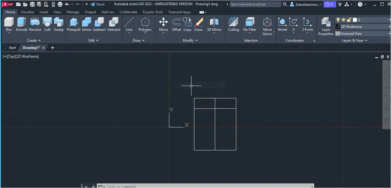
- Draw a rectangle of dimensions 10'*12'6"
- Draw a line of length 10'distance of 2'6" from the top edge of the rectangle drawn above.
- Draw a line connecting midpoint of the top and bottom edge.
- Select the top edge of rectangle click on center grip and click on add vertex.
STEP-1(A):
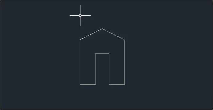
- Drag the top right corner of rectangle to the line drawn at 2'6".
- Darg the top left corner of rectangle to the line drawn at 2'6".
- Create recatngle symmetrical the midpoint of bottom edge of dimension 3'*7'
- Trim the bottom part of the door opening.
STEP-2: CREATING 3D VIEW.
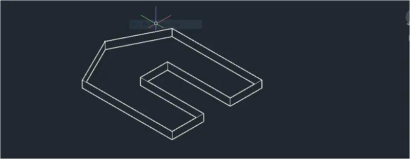
- Create a region by using region command inside the wall plan view.
- Change the view style control to shaded.
- Extrude the region created to distance of 9" to the top.
- The wall with door opening is created as shown below.
RESULT:
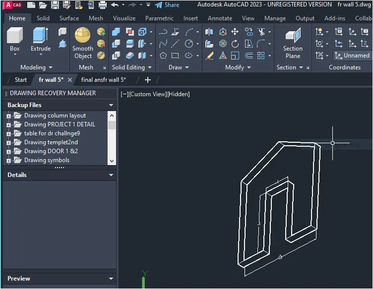
- The 3d model of a wall with door opening is drawn in the above steps. the result consist of model assigned with layers. the model is drawn using extrude command.Region command is used to draw surface to all the faces result is shown three differennt view style controls such as 2d wireframe ,hidden,and shaded.first the wall plan view is drawn with the door opening in 2d and then region is cretaed and extrude with door opening.
- All dimensions are in feet and inches.
1. 2D Wireframe model.
2. Hidden model
3.Shaded view.