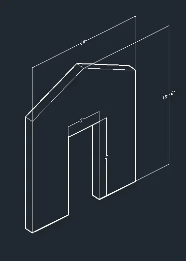
Creating various 3D Models like Furniture, Footing, Girder, Column drop with panel and Gable Wall in AutoCad
1.
Aim
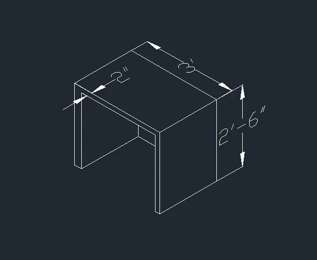
To create the given 3d furiniture model in autocad
Introduction
To create a 3D Furniture element as shown in the Figure.
Assume dimensions which are missing.
Procedure
UN command is given and units are set to engineering.
The precision is set to 0'-0'0"
Change the workspace to 3D modelling
Draw a vertical line of 2'6" using LINE command
Followed by line of 3' in the next horizontal direction and another line of 2'6" at the bottom.
Draw another line inside this lines like an offset at distance 2"
Extend these lines in the direction of x axis at distance 2'
Draw the inner lines by assuming the inner cube
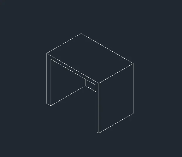
Mark the dimensions with the help of UCS command and DIMLINEAR command
Result
Thus the give 3d furniture element is drawn in autocad
2.
Aim
To create the 3d Model of an Isolated footing
Introduction
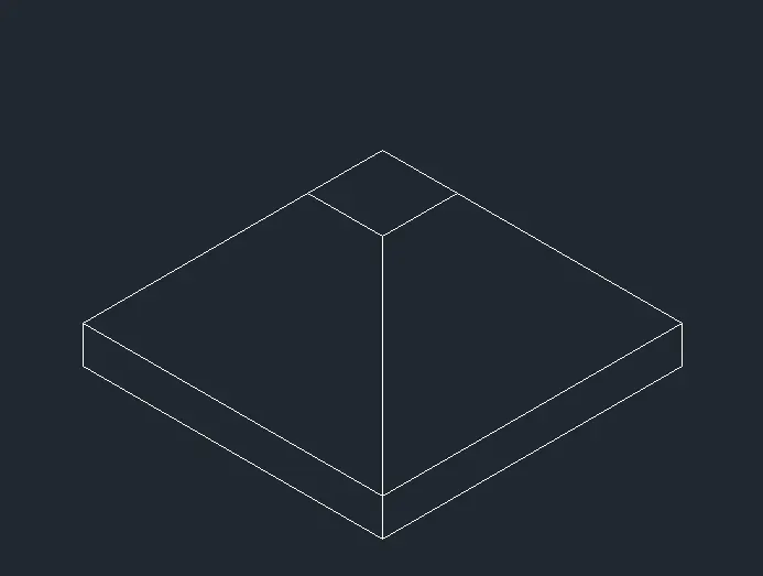
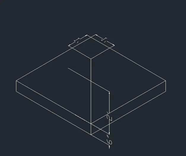
To create the 3d Model of an Isolated footing as shown in Figure.
And mark the dimensions
Procedure
UN command is given and units are set to engineering.
The precision is set to 0'-0'0"
Change the workspace to 3D modelling
The line is drawn in x axis and y axis at length of 4' each
Then offset both the lines at distance 6" and make as two rectangle
Draw a staright line 3' in z axis from middle
Then draw the square of 1'x1' at top
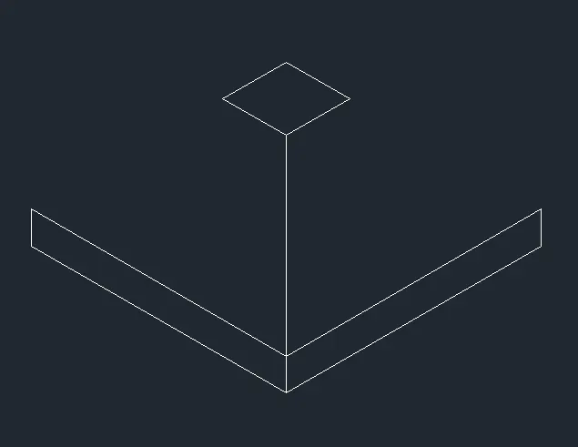
Then connect the square with x and y axis lines
Now mark the dimensions with the help of UCS command and DIMLINEAR command
Result
Thus the given 3D model of isolated footing is drawn
3.
Aim
To create the 3D view of AASTHO type girder
Introduction
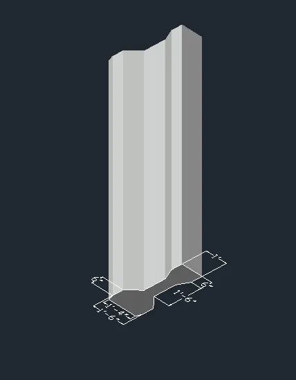
To create the 3D view of AASTHO type girder with the help of diagram and dimensions
Procedure
UN command is given and units are set to engineering.
The precision is set to 0'-0'0"
Change the workspace to 3D modelling
The outline is created using Top view from view cube.
It is created as per the given dimensions with LINE, OFFSET and TRIM tools.
The Home icon is clicked on the view cube.

BOUNDARY command is used to create a region within the outline.
It is then extruded as per dimensions using EXTRUDE command.
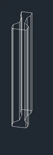
Then it is changed from 2D wireframe to realistic
Then the dimensions given are marked
Result
Thus the given 3D model of AASTHO type girder is drawn
4.
Aim
To create a 3d Model of a drop column with panel
Introduction
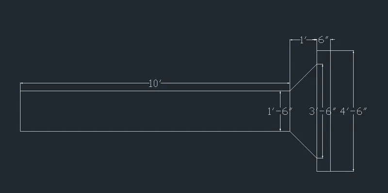
Create a 3d Model of a drop column with panel as shown in section and isometric view.
Procedure
Draw the first diagram given
With the required dimensions
Then mark the dimensions using DIMLINEAR
Then for the 3D model
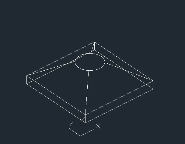
A rectangle is created of 4'6" dimensions using RECTANGULAR command.
Then it is extruded in z axis at distance of 6" thickness
Another rectangle of same imensions is drawn using RECTANGULAR.
A circle is drawn from the geometric center of the rectangle using CIRCLE command and moved for required distance in Z axis using MOVE command.
LOFT command given and the surface is created using the shapes.
It is then placed on the previously created cuboid using MOVE command.
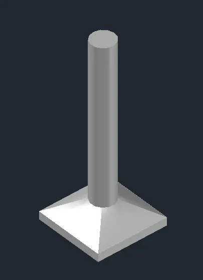
A circle is created on top of the previous circle using CIRCLE command.
It is extruded using EXTRUDE command for length of 10'
Then it is changed from 2D wireframe to realistic
Result
Created a 3d Model of a drop column with panel as shown in section and isometric view.
5.
Aim
To create the 3d model of a wall as shown in Figure
Introduction
Create the 3d model of a wall as shown in Figure.
Consider wall thickness as 9”.
Procedure
UN command is given and units are set to engineering.
The precision is set to 0'-0'0"
Change the workspace to 3D modelling
Using Line command and Trim command with the help of dimensions given
The oultine of the wall is drawn
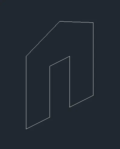
Using Region command create a region within its boundaries.
It is then Extruded using EXTRUDE command at length of 9"
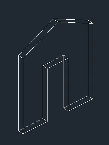
Then it is changed from 2D wireframe to hidden
Using DIMLINEAR dimensions are marked
Result
Thus the 3D model of the given wall is created