Creating various 3D Models like Furniture, Footing, Girder, Column drop with panel and Gable Wall in AutoCad
1}
AIM:
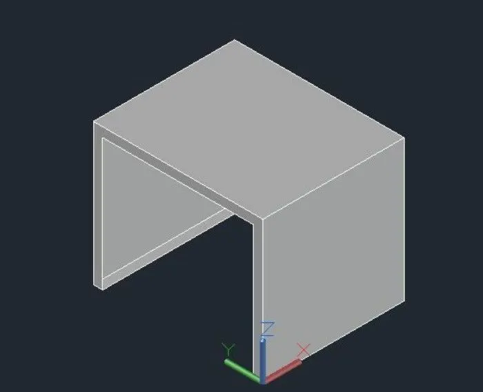
- To create a 3d furniture elements using the various commands in autocad.
Introduction By 3D view:
- The process of creating a mathematical representation of any surface of an object in three dimensions by using special software.
- A 3D model can even be represented as a two dimensional image by using the 3d rendering process.
- It enables the professional cretional and edition of 2D geometry and 3D models with solids ,surface and objects.
PROCEDURE:
- To create a new sheet from application of auto cad.
- Go to the setting and to change the view of the page from drafting to 3d modeling.
- Type ,UN`to set the units of current format of measure.
- Type LIMIT to set the maximum dimensions limits on the perticular page.
- First we take the top view of the page.
- Type,REC to create a rectangle with a dimension of 2`6 x 3`0.
- And then we take to a 3D custom view.
- Type ,3D ORBIT to view a 3D orbit viewport in the current viewport
- Then ,we take a all box dimension to create it from the origin point is [0,0,0]
- Next point we take to x direction of [@2`6",0,0]
- Type extrude to create a surface or solid of a 2D surface.
- Then we have to change the view of 2D wire ,shaded ,conceptional ,etc.
- Type ,3D FACE for allows to generate 3D faces By identifiying.
- To save the diagrams to particular file.
RESULT
- The diagram of 3D furniture elements is drawn as per dimensions using the software of Auto.
DIAGRAM
2]
AIM:
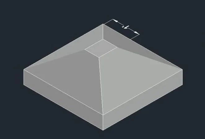
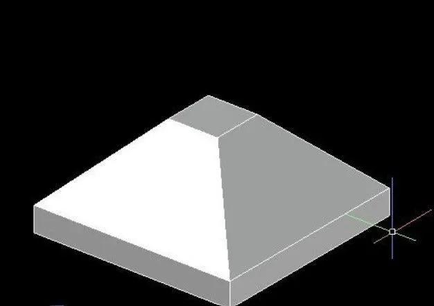
- To create a 3D model of an isolated footings using the various commands in autocad.
PROCEDURE:
- To create a new sheet from application of auto cad
- Go to the settings and to change the view of the page from drafting to 3D modelings
- type un to set the units of current format of measure.
- Type ,LIMITS to set the maximum dimension limits on the perticlar page.
- First we take the top view of the page.
- Type ,REC to create a rrectangle with a given dimensions.
- And we then take a 3D custom view
- The footing dimension is 4`0" x 4`0"
- The deapth of footing is 6" and reduce to the depth of 2 and width is 1`0
- COPY this commands is used to selected objects from a given square to destination, learning a copy att the originally selected location.
- MOVE - moves the object to the destination place from the source place.
- And then to join the all lines.
- Type "3D ORBIT `to view a 3D orbit viewport in the current viewport
- Type '3D ORBIT to view a 3D orbit viewport in the current viewport
- type ,3D FACE for allows to genetate 3d faces by identifying.
- To save the diagram to perticular file.
RESULT:
- The diagram of 3D model of an isolated footing is draw as per dimensions using the software of autocad.
DIAGRAM:
3]
AIM:
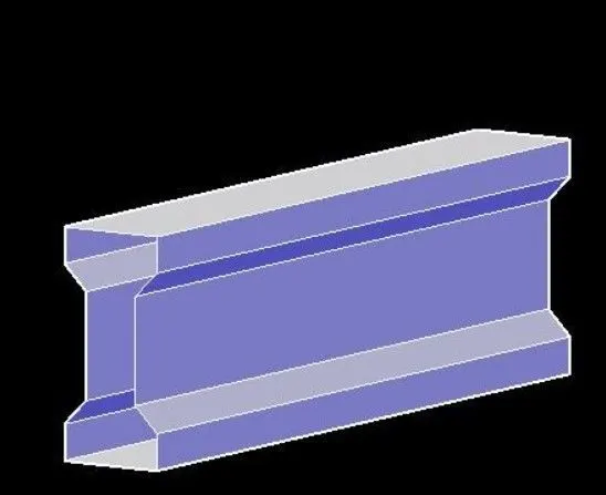
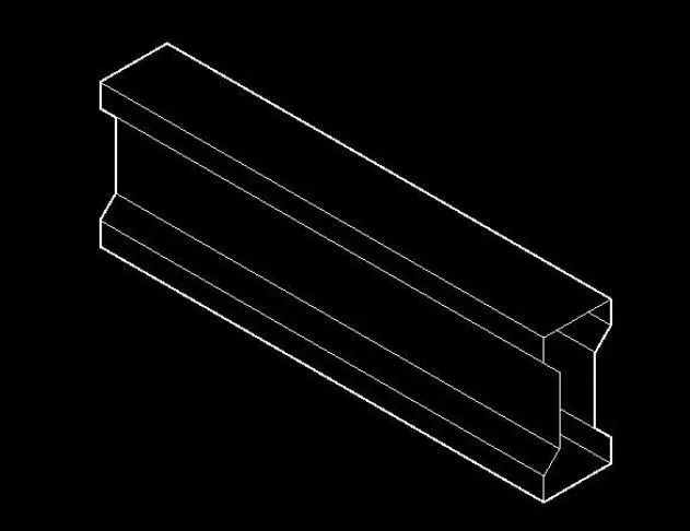
- To create a 3D view ot the AASTHO type girder using the various commands in Auto cad.
PROCEDURE:
- To create a new sheet from application of Auto CAD.
- Go to the settings and to change the view of the page from drafting to 3D modeling.
- Type "UN` to set the units of current form of measure.
- Type "LIMITS to set the maximum dimensions limits on the particular page.
- First we take the top view of the page.
- To take 'to create a line to draw the i section AASTHO Girder.
- The origin point is 0,0,0.
- The next point is [@!`6",0,0]
- The next point is [@0,0,6}
- The next point is [@6'<0<135]and to follow the all given dimension to draw the sections.
- Type ,3D ORBIT ,to view a 3D orbit viewport in the current view port
- Type 3D FACE for allows to generate 3D faces by identifying.
- Type 'REGION to convert objects that encloses an area into a 2D region objects.
- Type 'EXTRUDE To create a surface or solid of a 2D surface or a 3D curve.
- The extrudu length of the section girder is 10 feet.
- Then we have to change the view of 2d wire shaded conceptional etc.
- To save the diagram to particular file.
RESULT:
The diagram of 3D type of AASTHO girder type is draw as per dimensions using the software of Auto Cad.
DIAGRAM:
4)
AIM:
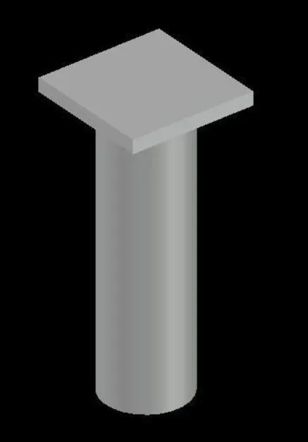
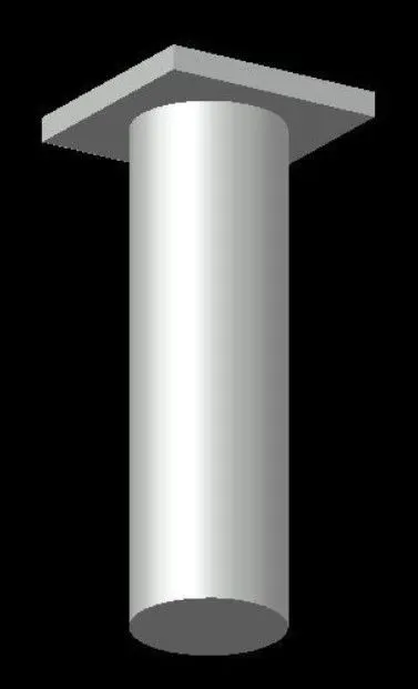
- To create the 3D model of a drop coloumn with panel using the various commands in Auto cad.
PROCEDURE:
- To create a new sheet from application of auto cad .
- Go to the settings and to change the view of the page from the drafting to 3D modeling.
- Type "UN to set up the units of current format of measure.
- Type limits to set up the maximum dimensions limits on the particular page.
- First we take the top view of the page.
- Type 'REC to create a rectangle with a given dimensions.
- And then we take to a 3d custom view
- To choose the top view of page.
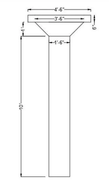
- The rectangular size is 4`6
- Type "c to create a circle options.
- The coloumn cap height id 1 feet
- The coloumn head thickness is 6 inch,
- The height of the coloumn is 10 feet.
- COPY _this command is used to selected objects from a given square to destination learining a copy at the originally selected location.
- MOVE - moves the object to the destination place from the source place.
- After completed the copy of rectangle to make the box like structure of coloumn head.
- After we take to draw a circle of diameter of 1"6.
- Type EXTRUDU To create a surface or solid of a 2D surface or a 3D curve.
- The extruded length of the circle coloumn with a negative direction of z is 10 feet.
- Type 3D ORBIT to view a 3D orbit viewport in the current viewport
- Type 3D FACE for follows to generate 3D faces by identifying
- Type REGION to convert objects that encloses an area into a 2D region objects.
- To save the diagram to perticular file.
RESULT:
- The diagram of 3d model of a coloumn with drop panel is drawn as per dimensions using the software of auto Cad.
DIAGRAM:
5)
AIM:
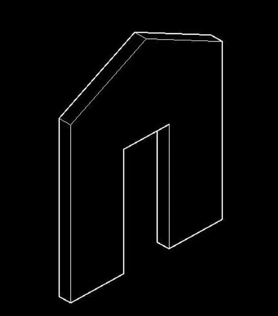
- To create a 3D model of wall using the various command in auto cad.
PROCEDURE:
- To create a new sheet from application of Auto Cad.
- Go to the setting and to change the view of the page from drafting to 3D modeling.
- Type UN to set the units of current format of measure.
- Type limits to set the maximum dimensions limits on the particular page.
- First we take the top view of the page.
- Before we start the 3D work to create a plan of wall at 2D.
- To make the wall thickness of 250mm.
- To fix the door and wall opening from wherever we need.
- Type region to convertt objects that encloses an area into a 2D region objects.
- To save the diagram to particular file.
RESULTS:
- The diagram of 3D model of a wall is drawn as per dimensions using the software of Auto Cad.
DIAGRAM: