Creating various 3D Models like Furniture, Footing, Girder, Column drop with panel and Gable Wall in AutoCad
1. Create a 3D Furniture element as shown in the Figure. Assume dimensions which are missing.
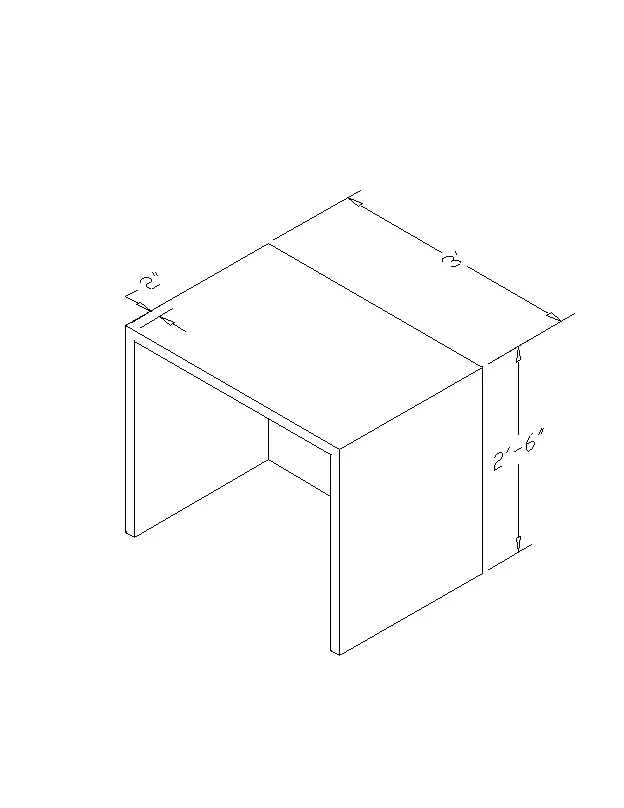
AIM:
To Create a 3D Furniture element in the specific dimension
INTRODUCTION:
- Plans and Sections are different types of drawings used by architects to graphically represent a building design
- A plan drawing is a drawing on a horizontal plane showing a view from above.
- An Elevation drawing is drawn on a vertical plane showing a vertical depiction.
- A section drawing is also a vertical depiction but one that cuts through space showing what lies within.
COMMAND ARE USED:
- Line command
- Rectangle command
- UCS command
- Dimlinear command
- Region command
- Extrude command
- Substract command
- Units command
- Dimstyle command
- 3Dface command
- Explode command
- Move command
- Copy command
PROCEDURE:
- First we set an unit as per the engineering and dimenion of inch have choosed
- Next we et limmax and limit spec @0,0 and 100,100
- Then z enter and a enter
- Then we choose 2d wire frame
- And then take line command vertically 2'6" and horizontally 3' to be an rectangle
- Offset to take 2" of the outer line
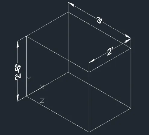
To be check the dimension 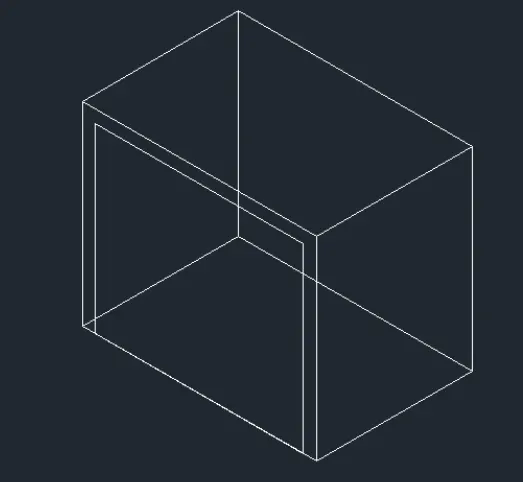
- To be take @3,0,0 and @0,0,-3 and connected the layers
- Conected the line for the box
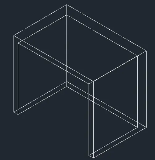
To be edit the unwanted lines and erase it
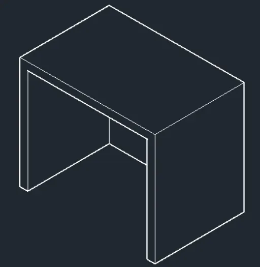
To be take region command and check the dimension
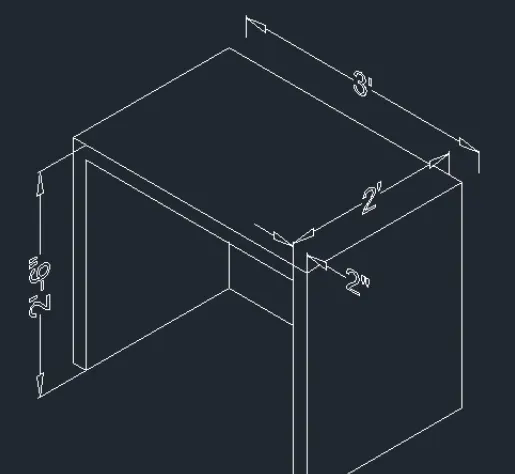
To change the view option 2d wireframe to slided to check the object and enter
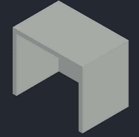
RESULT:
Finally we draw furniture using of autocad 3d
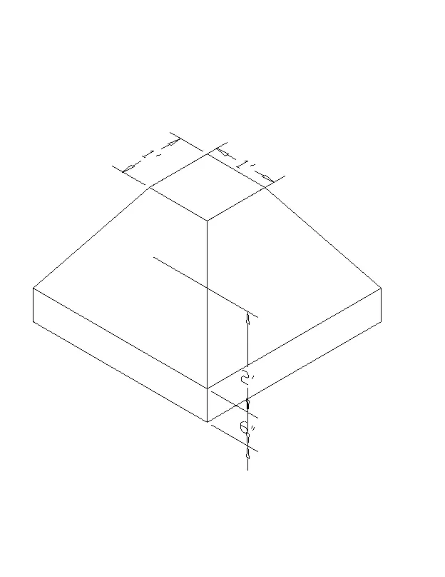
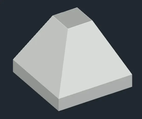
2. Create the 3d Model of an Isolated footing as shown in Figure.
AIM:
TO Create the 3d Model of an Isolated footing using of autocad 3d
COMMAND ARE USED:
- Line command
- Rectangle command
- UCS command
- Dimlinear command
- Region command
- Extrude command
- Substract command
- Units command
- Dimstyle command
- 3Dface command
- Explode command
- Move command
- Copy command
PROCEDURE:
- First we set an unit as per the engineering and dimenion of inch have choosed
- Next we et limmax and limit spec @0,0 and 100,100
- Then z enter and a enter
- Then we choose 2d wire frame
- Using of rectangle 2'
- Take offset 1' of the rectangle
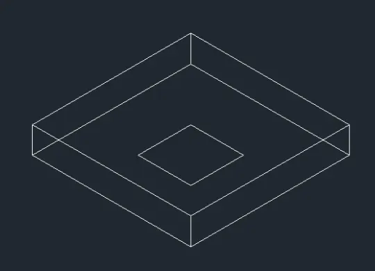
- To copy the rectangle to move the upper of the rectangle
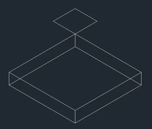
To extrude the rectangle at the 2'
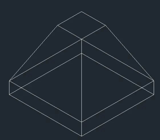
To coordinate system to use the connect the line
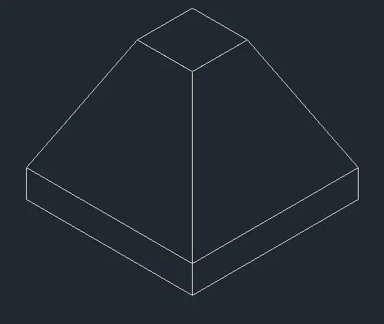
Choose the dimension command to check the dimension of the command
Choose the 2d wireframe to slided and select the objects
RESULT:
Finally we get the isolated footing using of the autocad 3d
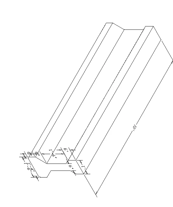
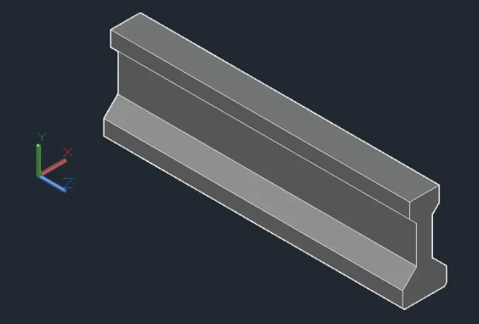
3. Create the 3D view of the AASTHO Type Girder.
AIM:
To create the 3d view of the aastho girder
COMMAND ARE USED:
- Line command
- Rectangle command
- UCS command
- Dimlinear command
- Region command
- Extrude command
- Substract command
- Units command
- Dimstyle command
- 3Dface command
- Explode command
- Move command
- Copy command
PROCEDURE:
- First we set an unit as per the engineering and dimenion of inch have choosed
- Next we et limmax and limit spec @0,0 and 100,100
- Then z enter and a enter
- Then we choose 2d wire frame
- To draw the line command over the 1'6" Horizontally
- Next we draw the 6" line to the vertically
- To we choose the fillet command use of the line to curve it
- And we do the line command extend the line 1'6" vertically
- Again Take the fillet option to same
- Take the 1' line to the horizontal
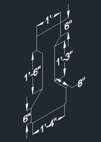
Check the dimension and take offset
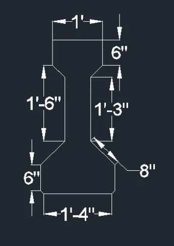
To extrude the object change the 2d wireframe to shaded
RESULT:
Finally we draw the isometric view using of autocad 3d
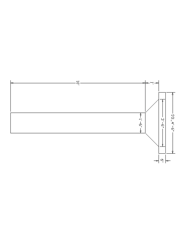
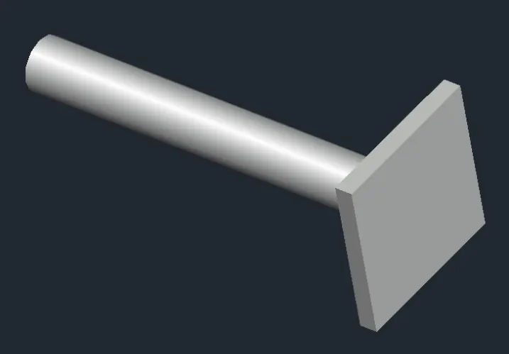
4. Create a 3d Model of a drop column with panel as shown in section and isometric view.
AIM:
To Create a 3D Isometric column
COMMAND ARE USED:
- Line command
- Rectangle command
- UCS command
- Dimlinear command
- Region command
- Extrude command
- Substract command
- Units command
- Dimstyle command
- 3Dface command
- Explode command
- Move command
- Copy command
PROCEDURE:
- First we set an unit as per the engineering and dimenion of inch have choosed
- Next we et limmax and limit spec @0,0 and 100,100
- Then z enter and a enter
- Then we choose 2d wire frame
- And then take line command vertically 10' offset to the dimension of 1'6"
- Using of the line command 1' widely to the line inclined 45 degree
- And take 4'6" Vertically through the x direction
- Take offset of the current value
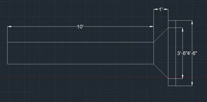
- To check the view option to change it
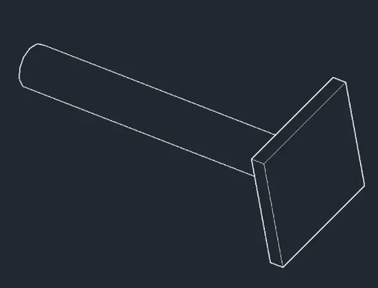
To exclude the section uing of the exclude command
To take the 2d wireframe to shaded
RESULT:
Finally we draw the isometric view of the column panel
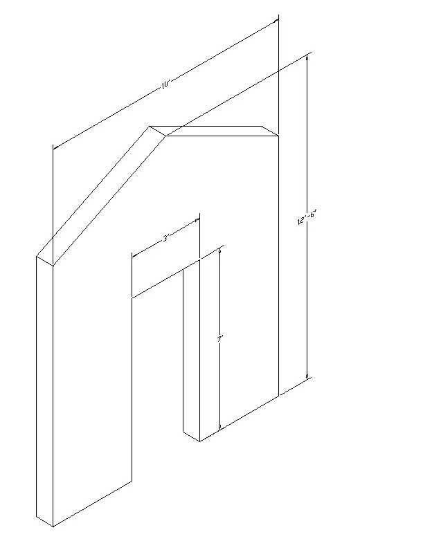
5. Create the 3d model of a wall as shown in Figure. Consider wall thickness as 9”.
AIM:
To create the wall at the thickness of 9" using of autocad 3d
COMMAND ARE USED:
- Line command
- Rectangle command
- UCS command
- Dimlinear command
- Region command
- Extrude command
- Substract command
- Units command
- Dimstyle command
- 3Dface command
- Explode command
- Move command
- Copy command
PROCEDURE:
- First we set an unit as per the engineering and dimenion of inch have choosed
- Next we et limmax and limit spec @0,0 and 100,100
- Then z enter and a enter
- Then we choose 2d wire frame
- To draw the line command over the 10'
- Next we draw the 5' at the 225 degree line to the vertically
- To take the offset 9" to the line
- To create the door opening of the wall
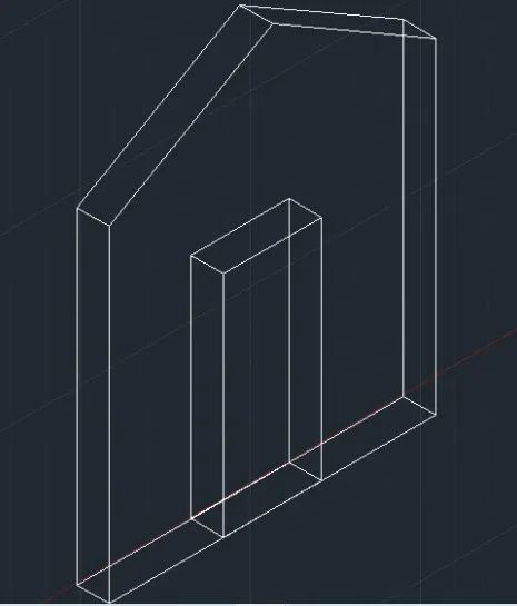
To remove the unwanted lines and exlude the object change the 2d wireframe to the shaded

RESULT:
Finally we draw the 9" Wall using of autocad 3d